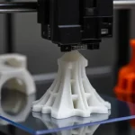
CNC machining is a subtractive manufacturing method, which means it removes material from a solid block (known as a blank or workpiece) using various cutting tools. This is a fundamentally different way of manufacturing compared to additive (3D printing) or formative (injection molding) technologies.The material removal mechanisms have significant implications on CNC’s benefits, limitations, and design restrictions. More on this in our guide.
What Is CNC Machining?
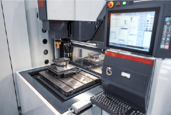
CNC(Computer Numerical Control)machining is a manufacturing process in which a computer controls machine tools according to preprogrammed instructions to cut and shape a workpiece into the desired part.
Due to its high level of automation, CNC can produce parts with exceptional accuracy, versatility, and efficiency at a competitive cost. This makes it a popular choice in today’s manufacturing sector, where labor costs are rising and precision requirements are also increasing.
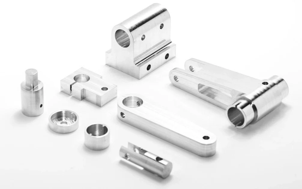
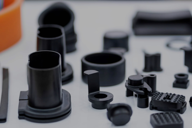
Another key advantage of CNC machining is its ability to work with almost any material. The most common CNC machining materials include metals (aluminum and steel alloys, brass, etc) and plastics (ABS, Delrin, nylon, etc). CNC machines can also handle foam, composites, and wood.
However, CNC machining has some limitations tied to its subtractive nature. For instance, certain internal structures or very complex geometries can be difficult or impossible to achieve. That’s why CNC is often compared with additive manufacturing (3D printing) and forming technologies (injection molding) when choosing the most suitable production method. (We’ll discuss this further later in the guide.)
History of CNC Machining
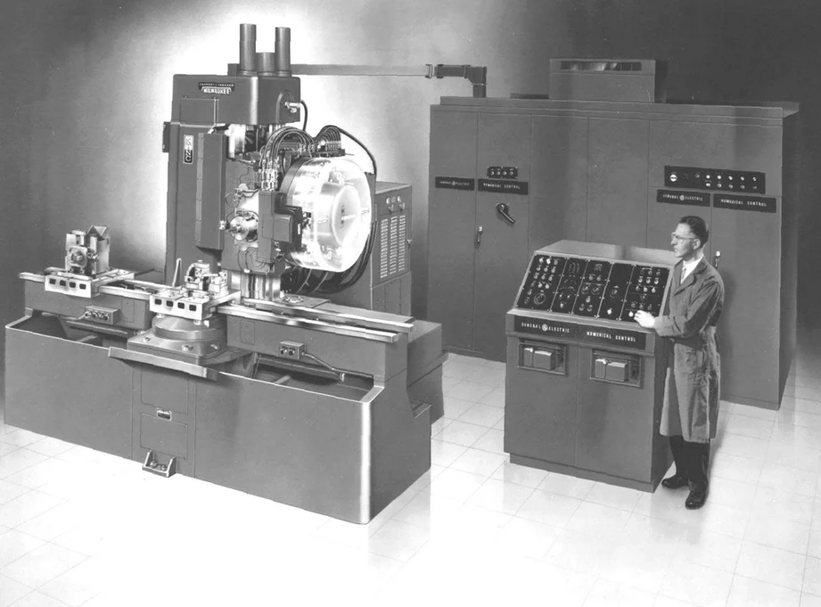
The origins of CNC machining date back to the late 1940s, driven by the aerospace industry’s urgent need for high precision, complex parts. As aircraft designs became more sophisticated, manual machining could no longer meet accuracy or efficiency demands. To address this, American engineer John T. Parsons partnered with MIT in 1949 to develop the world’s first numerical control (NC) system, using punched tape to guide machine movements—marking the beginning of manufacturing automation.
During the 1950s and 1960s, numerical control technology matured as early computers were integrated to enhance control accuracy and programming flexibility. In the early 1970s, the advent of digital microprocessors replaced analog controllers, giving rise to modern CNC. CNC expanded beyond milling and turning to include grinding and electrical discharge machining (EDM), enabling more diverse and higher precision manufacturing.
The advent of CAD/CAM in the 1980s transformed part programming: designers could draw a model in CAD software and automatically generate CNC toolpaths. In the 1990s, controls became more compact, spindles ran faster, and user interfaces grew ever more intuitive. As designers demanded tighter tolerances and greater complexity, multi-axis systems—especially 5-axis machines—rose to prominence, enabling entire parts to be machined in a single setup. In the early 2000s, the emergence of high-performance materials and demand for customized production further drove the adoption of advanced multi-axis centers.
Today, CNC machining is evolving rapidly through its integration with AI, IoT, and real-time monitoring systems. From its aerospace origins to its role as a cornerstone of Industry 4.0, CNC machining has undergone a remarkable journey and continues to advance.
How Does CNC Machining Work?
Although you’ll find that each CNC machine operates and is programmed slightly differently, they all follow these four basic steps:
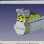
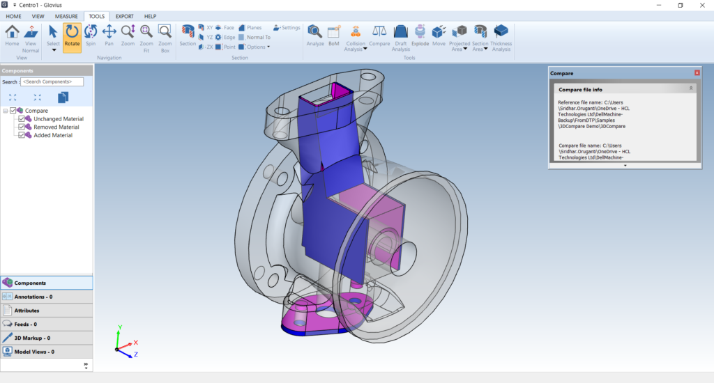
Step 1: Prepare a CAD Model
This involves creating a fully detailed 3D CAD (Computer-Aided Design) model of your part in software such as SolidWorks, Fusion 360, or similar. Make sure the model includes all critical geometry—dimensions, tolerances, hole patterns, threads, fillets—and any manufacturing notes.
Step 2:Convert the CAD Model into CNC Ready G Code
CNC machines can’t read a CAD model directly. Therefore, you must convert the model into a CNC-readable file called G-code. You can do this in CAD/CAM software such as Fusion 360, which has built-in CAM (Computer-Aided Manufacturing) tools to export G-code with a single click, or in dedicated CAM packages like Mastercam or Edgecam for more advanced toolpath generation. The resulting G-code contains everything the CNC controller needs—including toolpaths, spindle speeds, feed rates, and axis movements—to machine your part accurately.
Step 3: Preparing the CNC Machine
Next, the operator prepares the machine by checking its overall condition—confirming that all axes are properly lubricated and inspecting the lead screws and guideways for wear or damage. Then they load the required tools (either manually or via the automatic tool changer), clamp the workpiece securely in place, and, if needed, run a dry cycle to verify the toolpaths before cutting.
Step 4: Executing the Machining Operation
The operator starts the machining cycle by selecting the G-code program on the CNC control panel and pressing “Cycle Start.” The machine follows those instructions—moving the tool (or workpiece), activating coolant, and changing tools automatically as needed—until the cycle completes or is halted. Once it ends, the operator removes the finished part for inspection.
Common Types of CNC Machining Processes and the Machines Used
CNC machining refers to a family of computer-controlled cutting processes performed on various machine tools. Each operation suits specific part geometries, materials, tolerances, and functional requirements. Simple parts can often be produced with a single operation, while complex parts typically require a combination of multiple operations.
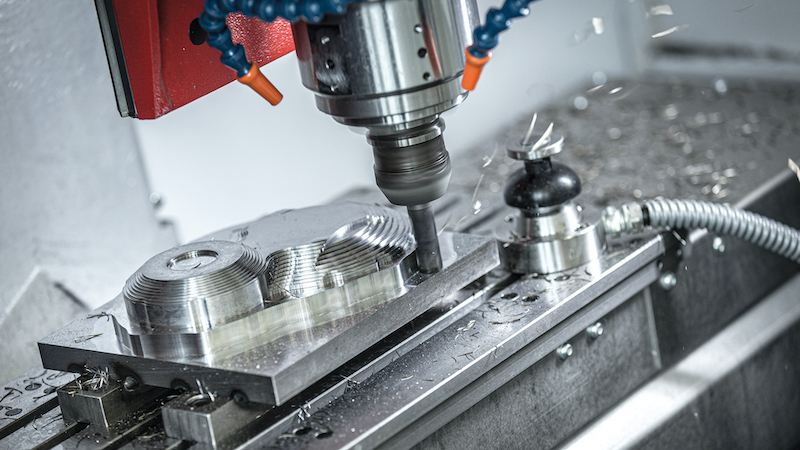
CNC Milling
CNC milling is the most common CNC machining process, and in many shops “CNC machining” and “CNC milling” are used interchangeably. In CNC milling, a rotating, multi-point cutting tool called a milling cutter moves relative to the workpiece to remove material. The ease of cutting depend on the sophistication of the CNC mill.
The most common types are 3-, 4-, and 5-axis milling machines.
3-Axis Milling Machines
3-axis mills move the cutting tool along three linear axes relative to the workpiece (X: left–right, Y: front–back, Z: up–down). They’re the most common CNC machines because they can produce nearly all basic geometries. They’re easy to program and operate, with relatively low start up costs. However, tool access is limited:certain areas might be impossible to reach or require manual re indexing of the part, which can reduce overall accuracy.
4-Axis Milling Machines
A 4-axis mill adds a rotary fourth axis—usually called the A axis—that rotates the workpiece around one of the linear axes (most often the X axis). This enables machining around cylindrical parts (like shafts, flutes, helical grooves) in one setup, reducing repositioning and fixturing time. However, on most 4-axis (3+1) machines, the A axis only indexes to fixed angles rather than rotating continuously during cutting.
5-Axis Milling Machines
A full 5-axis mill adds two additional rotary axes (typically A and B, or A and C), allowing the table or cutting head to rotate and tilt so the cutter can approach the workpiece from almost any angle. Unlike 3+2-axis machines, a full 5-axis machine moves all five axes simultaneously throughout each cutting operation, enabling the production of complex, free-form geometries with an accuracy and surface finish that no other technology can match. Naturally, these advanced capabilities come with higher costs—both for the machinery itself and for the highly trained operators required.
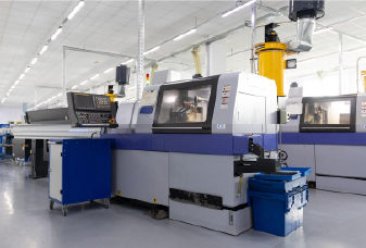
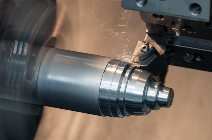
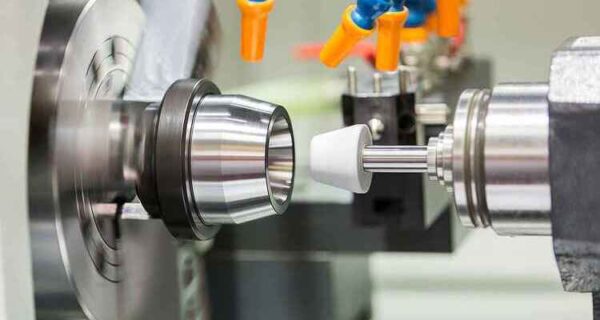
CNC Turning
In turning, the workpiece is held on a high speed rotating spindle. The cutting tool does not rotate and moves in the radial (X) and axial (Z) directions to shape the part. CNC turning is commonly used for cylindrical parts and delivers higher throughput and lower cost per unit than CNC milling.
There are two main types of CNC turning machines:
CNC Lathes
CNC lathes usually refer to 2 axis turning machines. They operate on the Z axis (along the spindle’s length) and the X axis (radially toward or away from the workpiece’s center). As the simplest type of CNC turning machine, they can perform basic operations—turning diameters, facing end surfaces, and boring or drilling along the centerline—with high precision. However, they cannot mill or drill features offset from the central axis.
CNC Turning Centers
A CNC turning center is a lathe enhanced with additional axes (often 3 to 5 in total) and live tooling capabilities. In other words, any CNC turning machine with more than two axes or with milling capability is called a “turning center.“
Turning centers can machine complex rotating parts in one setup: parts that are mostly rotationally symmetric but have features like off-center holes, milled flats, drill cross-holes, tap threads,or multiple machined sides. The trade off is higher equipment cost and more involved CAM programming.
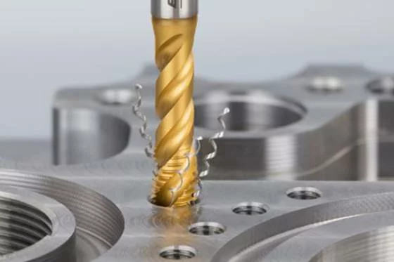
CNC Drilling & Tapping
CNC drilling automatically feeds a rotating drill bit into the workpiece at programmed positions, spindle speeds, and feed rates. A tapping head then cuts internal threads in the same setup. These hole making functions are often built into CNC mills or turning centers.
CNC Grinding
Grinding is typically a secondary operation after milling or turning. A rotating abrasive wheel removes minute amounts of material to achieve ultra-tight tolerances (down to millionths of an inch) and mirror-like finishes. Surface grinders flatten parts, while cylindrical grinders finish round shafts or bores.
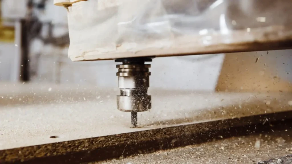
CNC Routing
CNC routers operate like milling machines, moving a cutting tool along the X-, Y-, and Z-axes to remove material. They use lighter, high-speed spindles and large work beds optimized for soft materials (wood, plastics, composites), enabling faster roughing cuts at the expense of rigidity and precision.
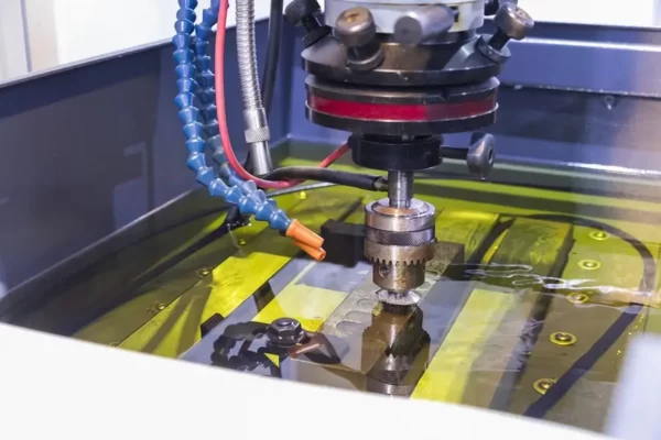
Electrical Discharge Machining (EDM)
EDM doesn’t “cut” in the traditional sense; instead, controlled electrical discharges erode material from hard-to-machine metals. There are two main types of EDM machines:
Wire EDM: Uses a thin, continuously fed wire to erode precise, intricate shapes.
Sinker (Die-Sinker) EDM: Uses a shaped electrode to form cavities and deep details.
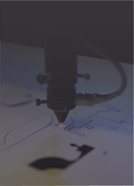
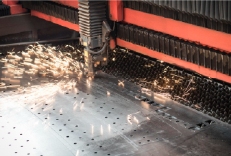
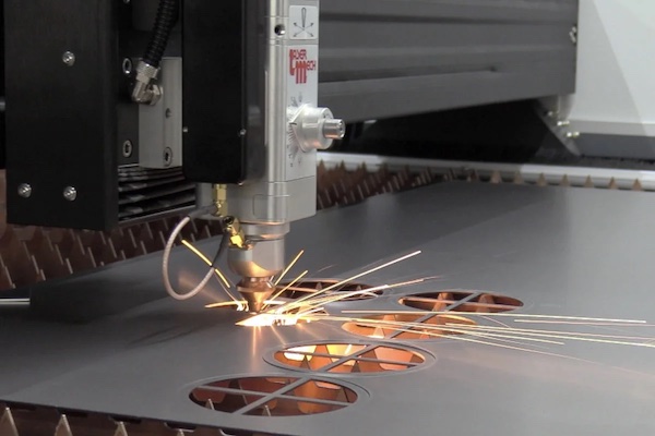
CNC Laser/Plasma/Waterjet Cutting
These are non-contact cutting processes that use different energy sources to slice sheet or plate materials: laser cutters direct a focused light beam for ultra-precise cuts in thin metals and non-metals; plasma tables generate an ionized-gas arc to cut thicker conductive metals quickly and cost-effectively; and waterjet cutters blast a high-pressure stream of water mixed with abrasive particles to cut virtually any material without a heat-affected zone, though they have higher operating costs.
Benefits & Limitations of CNC Machining
Here are the key advantages and limitations of CNC machining. Use these to decide whether it’s the right technology for your application.
Benefits of CNC machining
Accuracy and Precision
CNC machines follow exact toolpaths based on programmed instructions, enabling highly accurate material removal. Standard tolerances are around ±0.125 mm (±0.005 in), while tolerances as tight as ±0.050 mm (±0.002 in) and even ±0.025 mm (±0.001 in) are achievable. Moreover, this level of precision remains consistent across production batches.
Wide Range of Compatible Materials CNC machining works with virtually any material of sufficient rigidity—metals, plastics, composites, even wood and foam can all be machined. This gives engineers the flexibility to choose the optimal material for each application. Moreover, because material is removed rather than altered, CNC machined parts retain the base material’s original physical properties.
Fast and Efficient
Advances in modern CNC systems, CAM software, and digital supply chains have greatly reduced production lead times. Once programmed, a CNC machine can run around the clock with minimal human intervention. You can often get a finished CNC machined part in just a few days, which is comparable to the turnaround of industrial 3D printing processes such as SLS. However, overall speed and efficiency still depend on the specific CNC machine and the complexity of the part.
Scalable Production
Unlike formative methods (injection molding), CNC machining requires no specialized tooling, making it especially relevant for one off custom parts and prototypes where upfront costs matter. CNC is also a very price competitive option for small to medium batch runs (tens to hundreds of units). By contrast, additive technologies (3D printing) do not scale as well—unit prices remain relatively stable regardless of quantity—while formative methods (injection molding or investment casting) only become economical at large volumes (typically thousands of parts) due to high tooling expenses.
Limitations of CNC Machining
Material Waste
Because CNC machining is a subtractive process, it typically generates 30 %–60 % scrap from the original stock. In practice, shops reduce waste by optimizing part orientation in the stock, using near-net-shape or forged blanks when available, planning multi-part nests, and recycling chips. With these strategies, well-planned jobs can cut scrap rates to around 20 %–30 %. Even so, compared to formative or additive processes, CNC machining still produces significantly more material waste.
Tool Access and Workholding Restrictions
Because CNC machining removes material from a solid block, every surface must be reachable by a tool with the appropriate shape and stiffness. Deep cavities, tight internal corners, and steep undercuts are often impossible to mill without special long-reach, bent, or 5-axis cutters—and even then, collision risks increase and surface finish can suffer.
Meanwhile, the workpiece must be clamped firmly; thin walls or complex contours may require custom fixtures or supports to prevent vibration and deflection.
Geometric Complexity with a High Cost
When a part’s geometry becomes very complex—freeform surfaces, steep undercuts, or multiple tilted faces—CNC machining costs rise sharply. Complex shapes require more intricate CAM programming, longer toolpaths, and finer step overs, which extend cycle times. Multiple setups or custom fixtures are often needed so cutters can reach every angle, adding labor and machine downtime. Specialized tooling further increases expenses.
High Initial Investment
CNC machining involves a high initial investment, many of its upfront costs are fixed and must be spread over fewer parts. These costs include programming, setup, machine calibration, and tooling preparation, all of which require significant time and skilled labor regardless of the quantity produced.
No Material Property Gradation
CNC machining always starts from a single homogeneous stock—every point in the finished part shares the same material properties (density, stiffness, etc.). Unlike some 3D-printing methods that vary composition or porosity layer by layer, you cannot create zones of differing elasticity, hardness, or density on a CNC mill or lathe. This limits CNC machining when a design requires gradual transitions in material behavior (for example, a rigid exterior blending into a flexible core).
Alternative Manufacturing Processes to CNC Machining
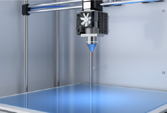
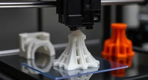
CNC machining is a versatile process widely used in part and product manufacturing. However, it’s not always the optimal method. 3D printing and injection molding are the two most common alternatives.
Table 1 provides a concise comparison of all three processes to help you quickly understand their respective advantages and limitations.
Key Factor
CNC Machining
3D Printing
Injection Molding
Batch Size
1–5000 pcs
1–500 pcs
≥ 1 000 pcs
Geometry Complexity
Medium–high (3-axis handles basic external shapes; 4/5-axis adds undercuts; deep cavities or intersecting channels need fixtures/EDM)
Very high (internal channels, lattices, freeform surfaces)
Medium to high (supports part features like moderate undercuts, side holes, and molded-in inserts; extremely intricate internal features require expensive mold components)
InitialSetup Cost
Medium to high (CAM programming, fixtures, tooling)
Low–medium (basic plastics/resins only need a build; metal or high-end resins andpost-processing cost more)
High (hard-tool molds start in low-five-figures USD; complexity, side cores, hot runners raise cost; soft molds ~$1 000–2 000)
Material Options
Metals, plastics, wood, composites, foam
Plastics, some metals, ceramics, composites
Thermoplastics, some thermosets
Production Speed
Programming/fixturing: 1–3 days; Machining time: minutes–hours per part; Batch of hundreds: 3–7 days
Print time per part: minutes–hours; Overall lead time: 1–3 days (batch size, post-processing vary); Metal/high-precision resin: ~1 week
Injection molding requires expensive tooling and cannot form internal lattices; CNC cannot mill interior lattice structures.
2
Drone aluminum frame
High strength, tight tolerances, batch of 300–1,000 units
CNC Machining
Metal 3D printing is cost prohibitive at this volume; CNC delivers better economics and material properties for aluminum frames.
3
Steel injection mold core
High precision, low quantity
CNC Machining
Injection molding produces plastic parts, not steel molds; while many metal AM processes (SLM/DMLS) can achieve near forged strength after heat treatment, CNC machining followed by heat treatment and grinding remains more reliable for long life mold cores.
4
Custom artistic case
Organic shape, single unit, plastic
3D Printing
CNC struggles with complex organic curves and would require custom fixtures; no tooling is needed for 3D printing.
5
Small plastic electronic enclosure
Snap fit features, internal supports, approximately 100 units
3D Printing
CNC is slow and wasteful for intricate internal features; injection molding tooling is too costly for only 100 units.
6
Mass production plastic housing
ABS/PC plastic, 10,000+ units
Injection Molding
High upfront mold cost is amortized over large volume
Metal 3D printing is expensive for large parts; CNC machining achieves the required tolerances more economically.
8
Aerospace lightweight Titaniumbracket
Complex lattice structure, low volume
Metal 3D Printing
Only 3D printing can produce intricate titanium lattice designs in a single build.
9
Mid-volume plastic connector
Simple geometry, cost control,1000 units
Injection Molding
Mold cost can be spread over 1,000 units, producing a lower per piece price than CNC or 3D printing.
Application Examples: Choosing the Right Process
5 Key Factors Affecting CNC Machining Cost and Reduction Tips
Controlling CNC machining costs isn’t just about negotiating lower prices—it’s about smart CNC machining design, efficient material choices, and strategic production planning. With the right approach, you can achieve both high quality and cost-effectiveness. In this section, we will briefly discuss what drives costs up in CNC machining and offer proven tips to reduce the cost of your CNC project.
Part Geometry Complexity
Part geometry complexity drives cost because intricate shapes require more machine time, additional tool changes, and multiple setups. Deep pockets, steep undercuts, angled holes, and thin walls necessitate smaller or extended-length tools, which cut more slowly and are prone to deflection. Long toolpaths and frequent repositioning increase cycle time and raise the risk of errors or scrap.
✅ Tips:
Add fillets to sharp internal corners so you can use larger diameter end mills and avoid custom tooling.
Keep pocket depths to no more than four times their width (depth ≤ 4× width) so standard length cutters can reach.
Maintain wall thicknesses of at least 0.8 mm for metals and 1.5 mm for plastics to prevent vibration and the need for multiple light passes.
Eliminate unnecessary angled or off axis holes; if an angled feature is essential, consider splitting the part into simpler subcomponents.
Ask your machinist for design for manufacturability feedback early, so you can catch and correct costly features before programming.
Material Selection
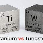
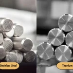
Choosing the right material affects cost by determining cutting speeds, tool wear, and scrap rates. Softer alloys like 6061 aluminum or POM cut quickly at higher feeds and preserve tool life. In contrast, stainless steel, titanium, and high temperature alloys require slower speeds, more frequent tool changes, and robust fixturing. Even within a material family, grades with better machinability can halve cycle times.
✅ Tips:
Whenever possible, select a material with high machinability that still meets your strength or corrosion requirements
Ask your vendor about alternative alloys or plastics that might cost less and cut faster.
Reduce excess thickness in costly metals by right sizing wall sections to only what’s structurally necessary.
Use near net shape blanks (forged or cast) for expensive alloys so you remove less material during each cut.
Factor in chip recycling rates; aluminum chips often have resale value, while harder alloys may not.
Order Quantity
Order quantity influences per piece cost because fixed expenses—like CAM programming, fixture fabrication, and machine setup—get spread over each part. When you run only a handful of pieces, those one time investments dominate the unit price. As volume increases, those costs become less significant, and material, cycle time become the main drivers.
✅ Tips:
Combine similar parts into a single production run so you share setups, zero offsets, and fixtures.
If you foresee needing more parts later, order a larger batch now to amortize programming and fixturing across more units.
Look for opportunities to order family plates or ganged parts, arranging multiple copies of small parts on one blank to reduce waste and setup time.
Schedule related jobs back to back so the same tooling and workholding can be reused.
Negotiate volume discounts with your shop if you can commit to a higher total quantity upfront.
Programming and Setup Time
Programming and setup time become significant when parts include nonstandard features such as decorative chamfers, engraved logos, or unusual hole sizes. Each extra face that requires flipping, every custom fixturing need, and each non standard toolpath adds hours of CAM work and machine downtime. Longer programming and frequent dry runs translate directly to higher shop rates.
✅ Tips:
Simplify geometry to use standard shapes, straight sided features, and common hole diameters (.1 mm or .5 mm increments) to leverage off the shelf drills and end mills.
Design parts so all critical features can be accessed in a single orientation (2.5D geometry), minimizing the need for multiple setups.
Share clean, well exported STEP or IGES files with proper face naming and no overlapping geometry to avoid CAM cleanup.
Remove purely cosmetic features—such as engraved text or chamfers—that add unnecessary tool paths.
Work with your machinist to identify which features are driving extra programming time and explore design alternatives.
Post-Processing Needs
Post processing needs such as polishing, anodizing, plating, or painting can add significant handling, masking, and curing steps. Each finish requires separate setup, movement between departments or vendors, and often rack or fixture changes—lengthening lead times and driving up cost.
✅ Tips:
Question whether a cosmetic finish is required; many internal or functional parts perform well “as machined” or with simple bead blasting.
If a finish is needed, consolidate treatments under one vendor to reduce shipping, handling, and scheduling overhead.
Specify surface finish requirements only on critical mating or exposed surfaces; accept standard milled finishes (Ra 1.6 µm–3.2 µm) elsewhere.
Choose finishes that can be applied in a single step—e.g., hard anodize instead of anodize plus paint—whenever possible.
Consider plating or coating that can be applied directly after machining without extensive masking, such as selective electroless nickel plating.
Work with Chiggo for Your CNC Machining Project
Chiggo is a leading precision CNC machining company in China with over 10 years of manufacturing experience. We operate state-of-the-art CNC equipment and have a professional team of engineers. Backed by a robust supply-chain network, we offer competitive pricing and reliable delivery times. Contact us now to experience our CNC machining services!