STEP files are a common language of 3D models in engineering and design. If you've ever needed to share a complex CAD model between different software programs, you’ve probably come across a STEP file. This article will discuss the STEP file definition, the format’s history, its benefits and drawbacks, comparisons with other formats, common use cases, and the software available to open or convert these files.
STEP File Definition and History
A STEP file is a standardized, neutral CAD format for exchanging 3D models between different systems. STEP stands for Standard for the Exchange of Product model data and is defined by the ISO 10303 family of standards. The clear-text file specified in Part 21 is commonly saved as .step or .stp; you’ll also see it referred to as a P21 or simply a “STEP file.” Development began within ISO technical committees in the 1980s, the first edition was released in 1994, and revisions followed in 2002 and 2016.
Unlike simpler 3D formats that capture only basic shapes, a STEP file can store the complete geometry of a model with high precision. It preserves curves, surfaces, and structure, often the entire part or assembly, rather than a rough approximation. The purpose is straightforward: make sharing accurate and easy across different software. If an engineer designs a component in one CAD program and another needs to open it in a different program, exporting to STEP keeps the model’s shape and details intact. In short, think of STEP as a “PDF for 3D models,” a universally readable format that retains full detail regardless of the software that created it.
Under the hood, STEP files are plain-text files defined by ISO 10303-21. They contain a header with metadata and a data section that lists the geometry in a structured way. You don’t need to read the code yourself, but this structure ensures precision across CAD programs.
Key Benefits of STEP Files
Cross-Platform Compatibility: STEP files are supported by nearly all major CAD programs, including Autodesk Fusion 360, CATIA, PTC Creo, Siemens NX, SolidWorks, and free tools like FreeCAD. This allows teams using different software to collaborate on the same design without conversion headaches.
Complete Geometry and High Precision: STEP files store exact geometry using math-based surfaces such as NURBS. Curved parts stay smooth, not faceted triangles, so dimensions and fits remain accurate.
Rich Data and Completeness: A STEP file can hold more than just shape. It can include assemblies, units, materials, and even tolerance data, which helps share a full product definition.
Editability and Reusability: When opened in CAD, STEP files become solid models that can be measured and modified. The original parametric history is lost, but the geometry is still clean and editable, unlike STL meshes which are hard to change.
Industry Acceptance: Because STEP is an ISO standard, it is required or preferred in industries like aerospace and automotive. Its long history also shows it is a reliable option for long-term archiving.
Efficient Compression: Although STEP files can be large, they compress very well. A zipped file is often only about 20% of the original size, which makes sharing easier.
Limitations of STEP Files
Large File Size and Complexity: STEP files describe precise curves and assemblies in text, so models can be heavy. Very large assemblies may open or save more slowly.
No Native Rendering or Visualization Data: STEP focuses on engineering information. It may include an engineering material name (for example, Aluminum 6061 or ABS plastic), but it does not store visual material appearances such as color, texture, gloss, transparency, lighting, or camera views. Most CAD programs will display a neutral-colored solid without scene setup. For rendering or game engines, the model typically needs to be tessellated into polygons first.
Not Ideal for Direct 3D Printing: Most slicers and 3D printers expect STL or similar mesh files. Some software can import STEP and convert it internally, but for printing workflows an STL is usually more convenient.
Storage Efficiency: Even when zipped, plain text STEP is less space efficient than compact binary formats. At repository scale, thousands of files or very large models can add up quickly.
Interoperability Quirks: While STEP is a standard, different CAD programs may interpret certain advanced entities or custom metadata differently. Geometry and basic assembly structure are generally reliable; issues, when they occur, usually involve annotations or other non-geometric data.
Common Use Cases and Industries for STEP
Who uses STEP files? Almost everyone in 3D design and manufacturing. Due to its accuracy and broad compatibility, STEP fits many day-to-day workflows.
Mechanical Engineering and Product Design
Engineers share parts and assemblies with suppliers, clients, and teammates who use different CAD tools. For example, a car part designed in one program might be sent as a STEP file to a supplier who uses another to analyze or manufacture it. A jet-engine manufacturer might provide a STEP model of an engine subassembly to an airframe partner so it integrates cleanly into their CAD environment.
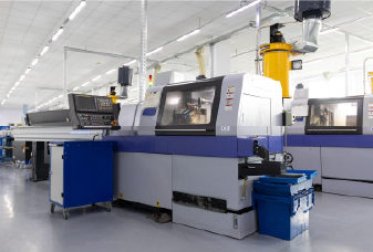
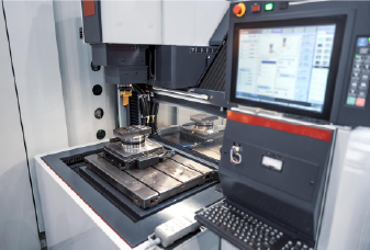
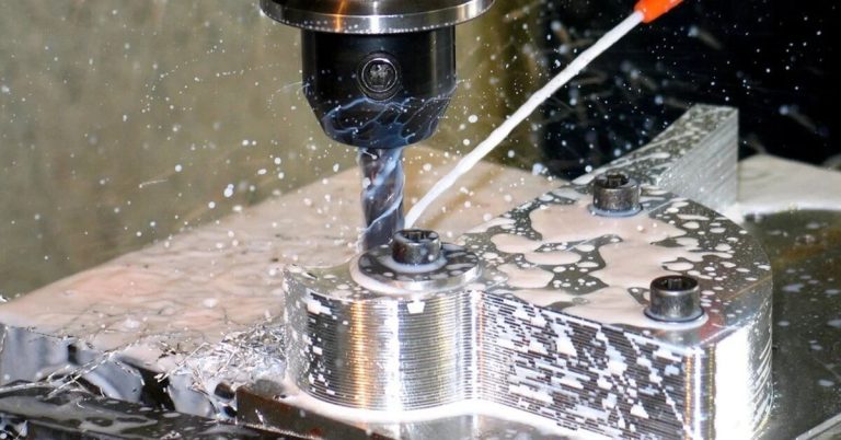
Manufacturing, CNC Machining, and Injection Molding
If you’re going from digital design to a physical part via machining, STEP is often the preferred input. CAM software reads STEP to generate toolpaths from exact curves and surfaces, avoiding the faceting issues common with pure mesh files. Mold makers also request STEP for cavity design to capture geometry faithfully.
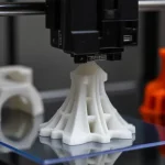
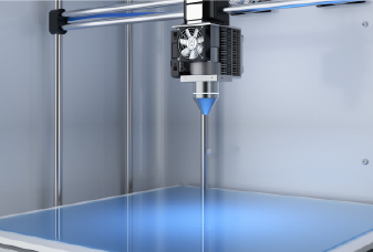
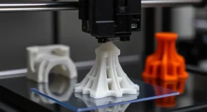
3D Printing and Rapid Prototyping
STL is the usual print file, but STEP is useful earlier for checks and adjustments. Some slicers can load STEP and tessellate on import. In practice, designers keep STEP as the design record, then export STL from CAD for printing; if changes are needed, they edit the STEP or native model and re-export.
Architecture and Construction
BIM formats like IFC dominate building workflows, yet STEP is used to exchange mechanical components within projects, such as HVAC units, escalators, and other equipment modeled in mechanical CAD. The geometry comes across accurately and can be converted to visualization formats when needed.
Simulation and Analysis
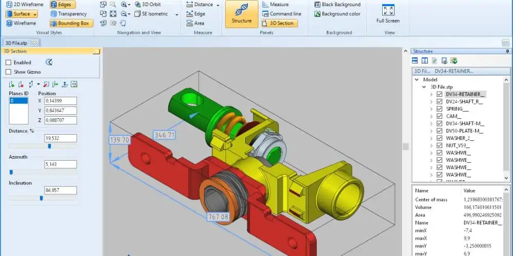
FEA and CFD tools import STEP, then mesh the geometry for analysis. In reverse-engineering work, scanned surfaces are often converted to STEP for further CAD edits or documentation.
Collaboration and Archiving
Many companies save a STEP file alongside native files for long-term access, even if the original software changes. Teams on different CAD systems also use STEP as the neutral handoff during design iterations, avoiding lock-in and keeping data accessible over time.
Software That Can Open or Convert STEP Files
To open or edit a STEP file, you’ll need a program capable of reading CAD models. Here are some options across various needs:
Before importing, check the settings: confirm units if the software doesn’t auto-detect them, and see whether surfaces need to be stitched into a solid (some tools import STEP as surfaces first). Most modern CAD programs handle these steps automatically.
To convert a STEP file, open it in a CAD or conversion tool and use Save As or Export to the target format (e.g., STL, IGES, OBJ). Converting a native model to STEP is done the same way. After any conversion, give the model a quick review to ensure geometry and details came through correctly.
What is the Difference Between a STEP vs STL vs IGES vs OBJ vs 3MF File?
Here is a table which shows the main differences between the most common 3D CAD model types:
Format
Geometry
Data Content
Accuracy / Editability
Best Used For
Main Limitations
STEP (.step, .stp)
Exact B-rep solids & NURBS
Units, assemblies, PMI/GD&T, engineering material names
High fidelity; editable as solids (no parametric history)
CAD exchange, machining, manufacturing, archiving
Large files, slower import/export, no visual textures
STL (.stl)
Triangle mesh
Bare surface mesh only
Approximate; mesh-only edits, not precise
3D printing, simple shape sharing
No units, metadata, or assemblies; faceted curves
IGES (.igs, .iges)
Curves & surfaces (NURBS); limited solids
Some units, limited metadata
Accurate surfaces but inconsistent; often needs stitching
Legacy systems, freeform surfaces
Outdated, less supported than STEP, weak solid handling
OBJ (.obj)
Polygon mesh (tri/quads)
Normals, UVs, textures via .mtl
Same accuracy as STL (mesh density); poor CAD edits
Visualization, games, textured 3D models
No units, assemblies, or engineering data
3MF (.3mf)
Mesh-based
Mesh + colors, materials, build info
Mesh-level fidelity; not CAD-editable
Additive manufacturing with color/material
Not parametric, not universal in CAD tools
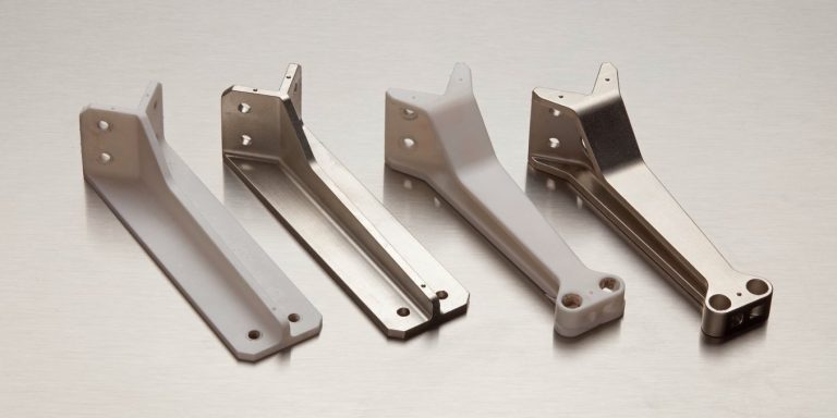
Start Your Next Project with Chiggo
At Chiggo, we help source and manufacture all your custom parts from the STEP files you’ve carefully designed. Whether you need CNC machined prototypes, injection molded parts, or production-ready assemblies, our team helps you move from design to finished product quickly and reliably.
With instant quoting, design-for-manufacturability feedback, and a full suite of manufacturing services, Chiggo is your trusted partner for custom production. Upload your CAD model today and see how fast, accurate, and seamless manufacturing can be.