Las piezas mecanizadas prevalecen en todas las industrias. Representan una categoría de componentes de ingeniería de precisión, hechas por procesos sustractivos a tolerancias estrictas y entregando geometrías complejas, precisión repetible y acabados superficiales superiores. Esta guía cubre los conceptos básicos de las piezas y los componentes mecanizados: lo que son, cómo se producen, sus ventajas y principios clave de diseño. También aprenderá sobre los materiales utilizados y sus aplicaciones.
¿Qué son las piezas y componentes mecanizados?
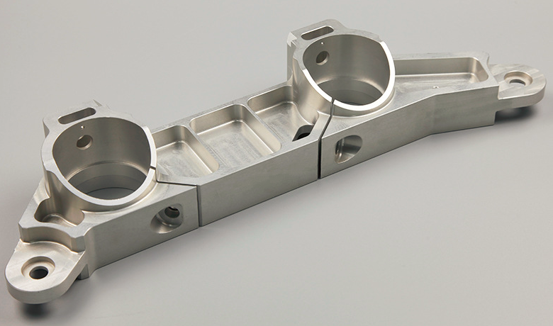
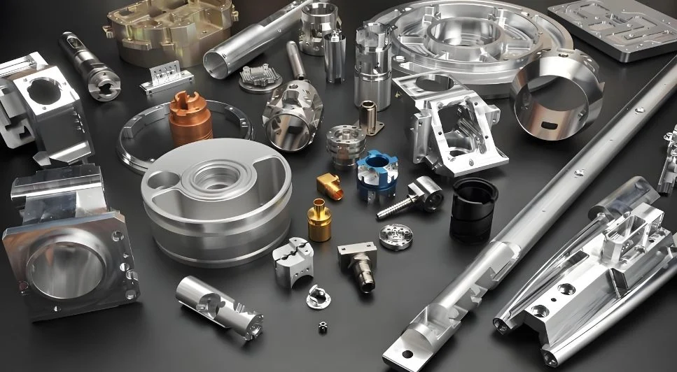
Las piezas y los componentes mecanizados son objetos de precisión creados al eliminar el exceso de material de un bloque sólido o "pieza de trabajo". Las máquinas de corte, como tornos, molinos, ejercicios y enrutadores, dan forma a la pieza de trabajo a la forma y al acabado deseados. Estas piezas pueden estar hechas de metales, plásticos u otros materiales que mantienen la estabilidad dimensional durante el corte.
El mecanizado se puede realizar de dos maneras principales:
Mecanizado manual:Operado por un maquinista experto que controla el movimiento de la herramienta directamente, a menudo utilizando volantes o palancas.
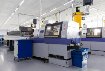
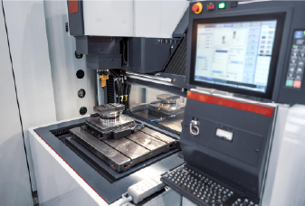
Mecanizado de CNC:Totalmente automatizado utilizando instrucciones digitales preprogramadas, permitiendo geometrías complejas, repetibilidad y alta eficiencia, particularmente para piezas personalizadas o de alta precisión.
La mayoría de los componentes complejos o personalizados se hacen en máquinas CNC para la máxima precisión y escalabilidad. No obstante, el mecanizado manual todavía tiene su lugar, especialmente para las partes rápidas, una de las partes fuera de lo que la configuración de un programa CNC tomaría más tiempo que simplemente cortar a mano.
En algunos casos, el mecanizado se usa como un proceso secundario o de acabado. Por ejemplo, una parte podría inicialmente fundida, forjada o moldeada por inyección, y luego someterse a mecanizado adicional para refinar sus características, como agujeros perforados, hilos tacados o superficies fresadas. A menudo se les conoce como piezas parcialmente mecanizadas o post-maquinadas.
Técnicas y procesos de mecanizado comunes
Desde agujeros simples hasta geometrías internas complejas, diferentes técnicas de mecanizado dan forma a las características clave de las piezas mecanizadas. A continuación se muestran algunos de los métodos de mecanizado más utilizados:
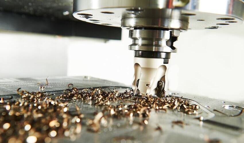
Molienda:Utiliza herramientas de corte múltiples giratorias para eliminar el material de una pieza de trabajo a lo largo de múltiples ejes. Este proceso es altamente versátil para crear superficies complejas, bolsillos, ranuras y formas contorneadas con alta precisión. Los tipos comunes de operaciones de fresado incluyen fresado facial, fresado final y molienda de tragamonedas.
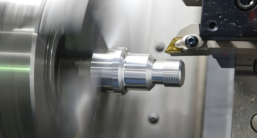
Torneado:La pieza de trabajo gira contra una herramienta de corte relativamente estacionaria para generar características cilíndricas (eje, varillas y bujes) con control dimensional apretado y acabados lisos.
Perforación:Una broca giratoria crea agujeros de varios tamaños y profundidades. Es uno de los procesos de mecanizado más fundamentales, ampliamente utilizados para agujeros a través de agujeros ciegos y agujeros roscados en partes mecánicas.
Broaching:Un brote dentado, con dientes progresivamente más grandes, corta material en una sola pasada. Es particularmente útil para cortar características internas como keyways, splines y agujeros no redondos.
Molienda:Una rueda abrasiva giratoria refina la geometría de la superficie y termina con tolerancias muy ajustadas. Esta técnica a menudo se usa como un paso final final para piezas de alta precisión.
Mecanizado de descarga eléctrica (EDM):Las chispas eléctricas en un material de obra de trabajo conductor de erosión dieléctrica de fluido, lo que permite la creación de formas intrincadas, esquinas afiladas y cavidades profundas en metales duros o delicados.
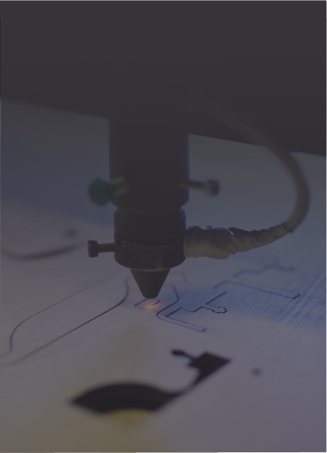
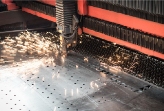
Corte láser:Utiliza un haz láser enfocado para derretir, vaporizar o quemar material, lo que permite un corte preciso y sin contacto. Es adecuado para metales, plásticos y otros materiales, particularmente en forma de lámina delgada.
Mecanizado ultrasónico:Las vibraciones ultrasónicas transmiten una suspensión abrasiva contra la pieza de trabajo, eliminando el material de materiales frágiles o sensibles al calor (por ejemplo, cerámica, vidrio) sin daños térmicos o tensiones mecánicas.
¿Cuáles son las ventajas de las piezas mecanizadas?
Las piezas mecanizadas CNC ofrecen varias ventajas clave sobre componentes impresos en 3D y de inyección de componentes moldeados. Estos beneficios incluyen:
No hay cantidad mínima de pedido (MOQ)
Una de las principales ventajas de las piezas mecanizadas es que no necesita una cantidad mínima de pedido para comprarlas. Puede solicitar un solo prototipo o cantidades muy pequeñas a pedido, sin las herramientas costosas y que requieren mucho tiempo requeridas para piezas moldeadas. Esto es especialmente útil para empresas más pequeñas, ya que reduce el inventario y el atado de capital y admite la producción personalizada.
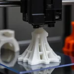
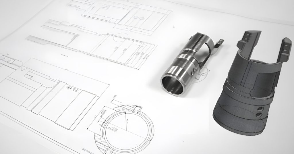
Buenos prototipos
Las piezas mecanizadas son adecuadas y asequibles como prototipos porque evitan las herramientas costosas y los requisitos mínimos de pedido. La programación y la configuración generalmente toman solo unos días, por lo que los equipos pueden iterar rápidamente los diseños y evaluar el ajuste y la función de cada versión en las pruebas del mundo real. El alta precisión y el acabado superficial superior del mecanizado CNC aseguran que los prototipos se parecen mucho a las piezas de producción final, incluso para geometrías complejas o detalles intrincados.
Además, el mecanizado admite una amplia gama de materiales, desde aleaciones de aluminio y acero hastaIngeniería de plásticos- Los desarrolladores pueden probar múltiples opciones en condiciones de funcionamiento reales e identificar el sustrato óptimo antes de comprometerse con la fabricación a gran escala.
Libertad de diseño
El mecanizado ofrece una libertad de diseño inigualable mediante el uso de herramientas de corte de múltiples eje para producir casi cualquier forma: bolsillos profundos, socavados, esquinas afiladas y contornos intrincados. Puede integrar características como hilos, jefes y keyways en una sola configuración, en lugar de diseñar inserciones separadas o agregarlas más tarde.
El moldeo por inyección, por el contrario, exige concesiones de diseño (espesores de la pared uniformes, ángulos de borrador y rutas de flujo consistentes) para garantizar el llenado de moho adecuado y la expulsión de la pieza. Una vez que se construye el molde, modificar ese diseño generalmente requiere cambios de herramientas costosos o incluso una reconstrucción completa del molde.
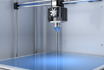
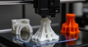
Incluso el proceso de impresión 3D, generalmente visto como uno de los mejoresprocesos de fabricaciónEn términos de libertad de diseño, tiene limitaciones. La mayoría de los métodos aditivos (especialmente FDM y SLA) no pueden construir voladizos empinados sin estructuras de soporte. Esos soportes agregan material, aumentan el tiempo de impresión y deben eliminarse después de la impresión, a menudo dejando marcas que necesitan lijado u otro acabado. Las piezas grandes o intrincadas pueden deformarse a medida que las capas se enfrían, y la construcción de capa por capa conduce a la fuerza anisotrópica y el "paso" visible en las superficies verticales.
Fortaleza
Las piezas mecanizadas se cortan de billets sólidos, que conservan toda la resistencia y la integridad del material del stock. Esto los hace estructuralmente superiores a las piezas impresas en 3D, que pueden sufrir debilidades entre capas y a piezas moldeadas, lo que puede requerir paredes más delgadas para consideraciones de flujo.
Tiempos de entrega más rápidos
Las piezas mecanizadas se producen mucho más rápido porque no hay moho o herramientas especiales para construir. Una vez que su modelo CAD está listo, se puede generar un programa CAM y enviar directamente a la máquina. Los centros CNC modernos pueden operar las 24 horas con una supervisión mínima, lo que permite fabricar piezas en solo unos días. Esta velocidad es especialmente beneficiosa para la prototipos rápidos, la producción de puentes y las necesidades de reemplazo urgente.
Acabado superficial
Las piezas mecanizadas pueden lograr acabados de superficie lisos y de alta calidad sin las líneas de flujo, flash o líneas de separación a menudo vistas en piezas moldeadas, o las líneas de capa de la impresión 3D. Al combinar altas velocidades de huso, velocidades de alimentación optimizadas y un refrigerante adecuado, el mecanizado puede lograr rutinariamentevalores de rugosidad (RA)por debajo de 0.8 µm, y con pases finales finos, incluso hasta 0.2 µm o mejor.
Calidad
Las máquinas CNC pueden contener tolerancias estrechas y ofrecer resultados consistentes de parte a parte. Si una característica dada, como un orificio de precisión que debe sellar perfectamente, requiere atención especial, el maquinista puede pasar más tiempo o hacer pases de acabado adicionales en esa función sin afectar el resto de la pieza.
Por el contrario, las piezas moldeadas por inyección dependen completamente de la precisión inicial de la cavidad del moho. Después de miles de ciclos, el desgaste de la herramienta y los ligeros cambios de proceso pueden redondear los bordes o cambiar las dimensiones, y no puede ajustar piezas individuales sin ajustes costosos de moho o operaciones secundarias.
Alteraciones fáciles
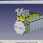
Debido a que las piezas CNC se producen directamente a partir de archivos CAD digitales, puede hacer cambios de diseño hasta que comience la fabricación. Esto es invaluable durante la I + D y la creación de prototipos: los ingenieros pueden ajustar las dimensiones o probar múltiples versiones sin costo adicional o material desperdiciado.
¿Cómo diseñar piezas mecanizadas?
Al diseñar piezas mecanizadas, generalmente es aconsejable seguir el diseño para los principios de fabricación (DFM) para garantizar la funcionalidad, la precisión y la rentabilidad. Afortunadamente, las piezas mecanizadas no son particularmente difíciles de diseñar cuando sigues la claveConsideraciones de diseño de mecanizadoabajo:
Espesor de la pared
Las paredes delgadas son propensas a la deflexión y la vibración durante el mecanizado, lo que puede provocar inexactitudes dimensionales y un acabado superficial deficiente. Como directriz general, el grosor de la pared no debe ser inferior a 0,8 mm para las piezas metálicas y 1,5 mm para las piezas de plástico.
Subvenciones
Los subcortes son características empotradas que no se pueden alcanzar con herramientas de corte estándar debido a la obstrucción de la geometría. Requieren herramientas especializadas, como cortadores en T o cortadores en forma de L, así como configuraciones adicionales de máquina y cambios de herramientas. Por esta razón, los socavos solo deben usarse cuando sea necesario para la función de la pieza, por ejemplo, cuando no se puede lograr una ranura de bloqueo, un keyway o una función de ensamblaje por ningún otro medio.
Al diseñar subproches en mecanizado, es mejor hacer sus dimensiones en milímetros completos para que coincidan con los tamaños de herramientas estándar. Los anchos subterráneos generalmente varían de 3 a 40 mm, con profundidades de hasta el doble del ancho.
Protuberancias
Las características sobresalientes altas y estrechas, como los jefes o los postes, son difíciles de mecanizar con precisión y pueden causar la charla de herramientas, la vibración o la distorsión de la pieza. Para mantener la estabilidad y la precisión, la altura de una protuberancia no debe exceder cuatro veces su ancho. Además, agregar costillas o filetes puede reforzar efectivamente las características sobresalientes y reducir la concentración de estrés, haciéndolas más estables durante el proceso de mecanizado.
Cavidades, agujeros e hilos
Las cavidades y los bolsillos no deben ser más profundos que cuatro veces su ancho para garantizar la evacuación adecuada de los chips y evitar la desviación de las herramientas. Debido a que las fábricas finales tienen un perfil circular, las esquinas internas siempre tienen un radio, así que evite especificar los bordes internos perfectamente nítidos.
Los agujeros generalmente se fabrican con brocas o fábricas finales. Dado que los bits de perforación vienen en tamaños estándar, combine los diámetros del orificio con las herramientas estándar siempre que sea posible. Además, limite la profundidad del orificio a cuatro veces el diámetro para mantener la estabilidad de la herramienta y la precisión de perforación.
Los hilos se pueden mecanizar hasta los tamaños pequeños (por ejemplo, M6 y debajo), pero deben equilibrar la resistencia y la eficiencia. Como guía, use una longitud de compromiso de al menos 1.5 × diámetro nominal (hasta un máximo práctico de 3 × diámetro). Más allá de eso, los hilos adicionales agregan tiempo de mecanizado y uso de herramientas sin un beneficio significativo de carga de carga.
Escala
El tamaño de una parte debe adaptarse a las capacidades del equipo de mecanizado. Para la mayoría de las operaciones de fresado, las dimensiones de piezas típicas no deben exceder las 400 × 250 × 150 mm. Las piezas más grandes pueden requerir centros de mecanizado verticales u horizontales avanzados. Ciertas máquinas de fresado de 5 ejes pueden manejar componentes de hasta 1000 × 1000 mm o incluso más. Para los procesos de giro estándar, el tamaño máximo factible es de aproximadamente Ø 500 mm × 1000 mm.
El tamaño mínimo de piezas generalmente está limitado por el diámetro de la herramienta y la precisión de la máquina. Por ejemplo, si una característica es más pequeña que la herramienta misma, no se puede mecanizar. En las máquinas estándar, el tamaño mínimo de la característica generalmente varía de 0.5 mm a 1 mm. Para piezas extremadamente pequeñas, se pueden requerir equipos de micro-maquinamiento o procesos de ultra precisión para lograr la geometría deseada.
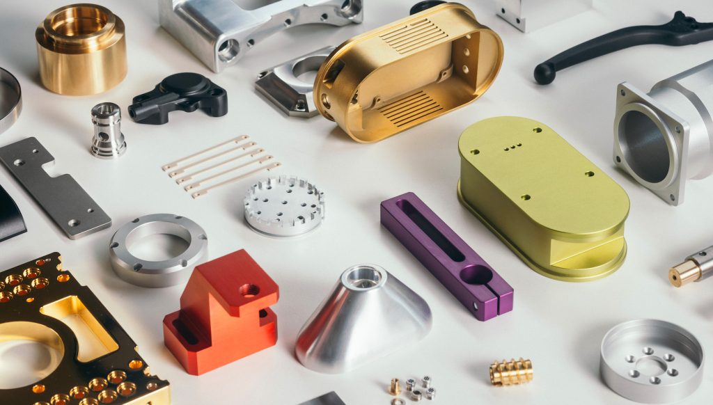
Materiales de pieza mecanizada
Las piezas mecanizadas se pueden hacer de una amplia variedad de materiales. El material de mecanizado CNC que selecciona influye en las propiedades mecánicas, como resistencia, peso y resistencia a la corrosión, y características de mecanizado como la velocidad de corte, el desgaste de la herramienta y el acabado superficial. Los materiales más suaves son más fáciles de cortar pero pueden deformarse; Los materiales más duros exigen alimentos más lentos y herramientas especializadas.
A continuación se presentan algunos materiales comúnmente utilizados para piezas mecanizadas:
Materiales compuestos:Resina epoxi, reforzada con fibra de carbono, fibra de vidrio, Kevlar
Cerámica:Alúmina, circonio, carburo de silicio, nitruro de boro
Acabados de superficie de pieza mecanizada
Se puede aplicar una variedad de opciones de postprocesamiento a las piezas mecanizadas para mejorar la textura, la apariencia y el rendimiento de la superficie. A continuación se muestran acabados de superficie comunes para piezas mecanizadas por CNC:
Como maquinado:Sin tratamiento de superficie adicional. Refleja la condición de superficie natural de la pieza a medida que sale directamente de la máquina. Se pueden visibles pequeñas marcas de herramientas y variaciones de superficie. Es adecuado para partes internas, no subméticas o puramente funcionales.
Bead volada:Los medios abrasivos se explotan en la superficie para crear una textura uniforme y mate. Ayuda a eliminar las rebabas, los bordes afilados y las marcas de mecanizado. Sin embargo, es importante tener en cuenta que el proceso de explosión elimina una pequeña cantidad de material de la pieza, lo que puede afectar tolerancias estrictas y características delicadas.
Anodizado:Un proceso electroquímico comúnmente utilizado en piezas de aluminio para mejorar la corrosión y la resistencia al desgaste. La anodización tipo II crea un recubrimiento decorativo y resistente a la corrosión disponible en varios colores. La anodización de tipo III (anodización dura) produce una capa más gruesa y densa, que ofrece una mayor abrasión y resistencia química.
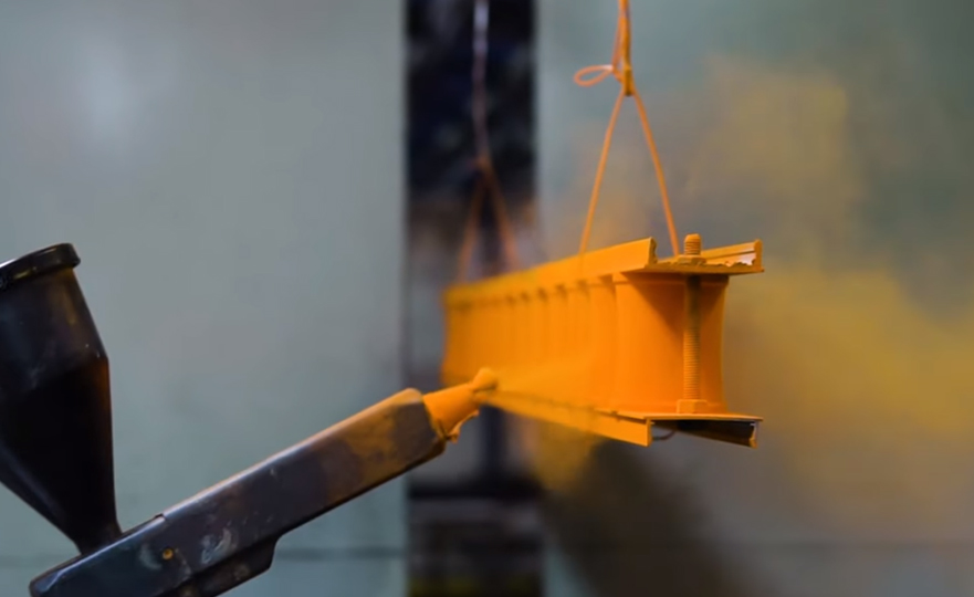
Polvo recubierto:El polvo seco se rocía sobre la superficie de la pieza, que luego se cura al calor en un horno para formar un recubrimiento duro y de color. Este acabado ofrece una capa fuerte, resistente al desgaste y resistente a la corrosión que es más duradera que los recubrimientos de pintura estándar.
Pulido:Un proceso mecánico que utiliza abrasivos finos o ruedas puliendo para lograr una superficie lisa y reflectante. El pulido mejora la estética y puede reducir la rugosidad de la superficie para los componentes que requieren un atractivo o atractivo visual.
Tolerancias de pieza mecanizada
Las tolerancias de mecanizado son el rango permitido de desviación dimensional, que muestra cuánto puede diferir una parte terminada de sus dimensiones de diseño nominal. Cuanto más apretado, mayor tolerancia, mayor sea la precisión del mecanizado, y mayor será la dificultad y el costo de fabricación. Los componentes que requieren ajustes precisos o funciones críticas exigen tolerancias estrictas, mientras que las piezas no críticas pueden haz una tolerancia más rentable, más rentables.
Existen varios estándares internacionales para tolerancias de mecanizado, siendo ISO 2768 uno de los más ampliamente adoptados. Este estándar proporciona tolerancias métricas generales (en milímetros) para dimensiones lineales y angulares sin requerir especificaciones de tolerancia individual. Clasifica las tolerancias en cuatro grados y ayuda a los fabricantes a reducir la ambigüedad, mantener la consistencia y optimizar los costos de producción. Vea las tablas a continuación:
Rango de tamaño básico en MM
Desviaciones permitidas en MM
F (bien)
m (medio)
C (grueso)
V (muy grueso)
0.5 hasta 3
± 0.05
± 0.1
± 0.2
-
más de 3 hasta 6
± 0.05
± 0.1
± 0.3
± 0.5
más de 6 hasta 30
± 0.1
± 0.2
± 0.5
± 1.0
más de 30 hasta 120
± 0.15
± 0.3
± 0.8
± 1.5
más de 120 hasta 400
± 0.2
± 0.5
± 1.2
± 2.5
Más de 400 hasta 1000
± 0.3
± 0.8
± 2.0
± 4.0
más de 1000 hasta 2000
± 0.5
± 1.2
± 3.0
± 6.0
Más de 2000 hasta 4000
-
± 2.0
± 4.0
± 8.0
La designación de la clase de tolerancia para las dimensiones lineales, según el estándar ISO 2768
Rango de tamaño básico en mm (lado más corto del ángulo en cuestión)
Desviaciones permitidas en grados y actas
F (bien)
m (medio)
C (grueso)
V (muy grueso)
hasta 10
± 1º
± 1º
± 1º30
± 3º
más de 10 hasta 50
± 0º30
± 0º30
± 1º
± 2º
más de 50 hasta 120
± 0º20 ′
± 0º20 ′
± 0º30 ′
± 1º
más de 120 hasta 400
± 0º10 ′
± 0º10 ′
± 0º15 '
± 0º30 ′
Más de 400
± 0º5 '
± 0º5 '
± 0º10 ′
± 0º20 ′
Las tolerancias generales para ángulos/dimensiones angulares
¿Cuáles son las aplicaciones de las piezas mecanizadas?
El mecanizado se utiliza en todas las industrias para producir componentes precisos y duraderos, como cuerpos de válvulas, engranajes, carcasas,sujetadoresy paréntesis, tanto en prototipos como de producción de escala completa. A continuación se presentan industrias clave que usan piezas mecanizadas:
Aeroespacial
La industria aeroespacial requiere piezas mecanizadas que cumplan con los más altos estándares de rendimiento y seguridad. Estos componentes deben soportar presión extrema, variaciones de temperatura y cargas mecánicas mientras se mantienen un peso mínimo. El mecanizado CNC admite geometrías complejas y tolerancias a nivel de micrones requeridos en este campo.
Aplicaciones típicas:
Cuchillas y carcasas de turbina
Componentes del sistema de combustible y montajes del motor
Pañales de tren de aterrizaje y soportes estructurales
Componentes satelitales y carcasas del sistema de comunicación
Médico
La precisión y la biocompatibilidad son primordiales en la fabricación de dispositivos médicos. El mecanizado CNC permite la producción de piezas de alta precisión con acabados lisos y tolerancias estrechas, adecuadas para implantes e instrumentos quirúrgicos de alto rendimiento. También admite una amplia gama de materiales de grado médico certificado.
Aplicaciones típicas:
Implantes ortopédicos (reemplazos de cadera/rodilla, tornillos de hueso)
Instrumentos y herramientas quirúrgicas
Carcasas de equipos de diagnóstico y subsistemas mecánicos
Implantes dentales y componentes intraorales
Automotor
El mecanizado CNC se usa ampliamente en ingeniería automotriz para producir componentes confiables de alta resistencia para transmisiones, sistemas de energía y ensamblajes de chasis. El mecanizado permite la rápida iteración en el ajuste del rendimiento y la creación de prototipos, al tiempo que respalda la producción a gran escala de piezas mecánicas de precisión.
Aplicaciones típicas:
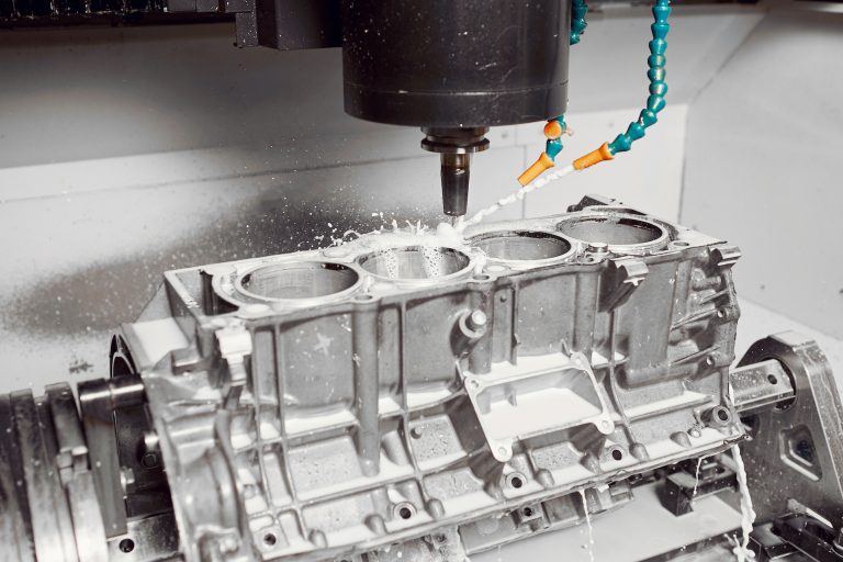
Bloques de motor, pistones, cabezales de cilindro
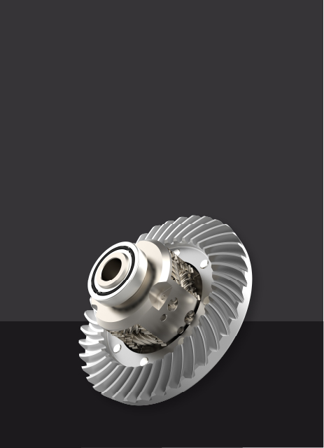
Componentes de transmisión: ejes, engranajes, carcasas
Piezas del sistema de frenos y sujetadores estructurales
Piezas de rendimiento o restauración personalizadas
Electrónica de consumo
En la industria electrónica, los componentes deben ser compactos y térmicamente confiables. El mecanizado CNC se utiliza para producir recintos, estructuras de enfriamiento y carcasas de conector con alta precisión dimensional y excelente acabado superficial, a menudo para la producción de bajo volumen.
Aplicaciones típicas:
Disipadores de calor y componentes de protección de EMI
Recintos de aluminio o plástico de precisión maquinada
Conectores, espaciadores y hardware de montaje
Prototipos de dispositivos personalizados
Los componentes mecanizados también se utilizan ampliamente en defensa, robótica, energía renovable y equipos industriales. Su fuerza, precisión y confiabilidad los hacen adecuados para piezas de alto rendimiento que operan bajo estrés mecánico, variación térmica y condiciones duras.
¿Cómo seleccionar proveedores de piezas de mecanizado?
Desde la calidad general del producto y la precisión del diseño hasta los detalles más finos de tolerancias estrechas y materiales especializados, seleccionar el proveedor de piezas de mecanizado adecuado es fundamental para el éxito del proyecto. En esta sección, describimos algunos factores clave a considerar al evaluar a los proveedores de mecanizado CNC:
Certificaciones:Busque proveedores con certificaciones ISO9001 o específicas de la industria que demuestren gestión de calidad y control de procesos.
Comunicación de ingeniería:Evalúe qué tan bien el proveedor comprende sus requisitos de diseño. Las respuestas claras y las preguntas perspicaces generalmente reflejan el mecanizado profundo saber cómo.
Reputación y referencias:Pregunte a otros equipos de productos sobre sus experiencias de proveedores. La retroalimentación de primera mano es a menudo el filtro más confiable.
Transparencia de la instalación:Si es posible, visite el proveedor o organice una auditoría virtual para evaluar el equipo, el flujo de procesos, la capacidad y las medidas de control de calidad.
Citas y plazos de entrega:Solicitar cotizaciones (RFQ) de múltiples proveedores para comparar los precios, la capacidad de respuesta, la flexibilidad y los plazos de entrega, especialmente para los envíos internacionales.
Para garantizar una colaboración más suave:
Siga los principios DFM (Diseño para mecanizado) en sus modelos CAD
Incluir dibujos 2D detallados con tolerancias estándar y notación
Use NDAS para proteger los diseños patentados
Aclarar las condiciones de pago: a menudo se requiere el pago para los primeros pedidos
Trabajar con Chiggo para piezas mecanizadas personalizadas
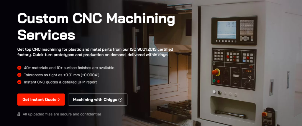
Chiggo es una oferta de socios confiablesServicios de mecanizado CNCPara sus prototipos rápidos y sus necesidades de piezas mecanizadas a pedido. Con una amplia experiencia en diversas industrias, entendemos la importancia de la velocidad y la precisión.
Nuestro taller de máquinas está equipado con centros de mecanizado avanzados y respaldado por un sólido sistema de gestión de calidad, lo que nos permite ofrecer componentes de alta calidad a precios competitivos y con plazos de entrega más cortos.Contáctenos hoy¡Para pedir sus piezas mecanizadas!