Este artículo proporciona consejos de diseño prácticos para el moldeo por inyección para ayudar a mitigar los errores comunes, mejorar la calidad del producto y reducir los costos al evitar cambios costosos de moho y reelaborar.
Descripción general del moldeo por inyección
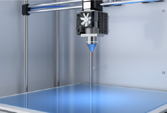
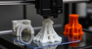
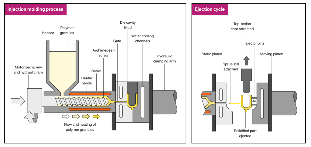
El moldeo por inyección es uno de los más rentablesproceso de fabricaciónpara producir altos volúmenes de piezas de plástico idénticas. En este proceso, los gránulos de polímeros se derriten primero y luego se inyectan bajo presión en un molde. Una vez que el plástico se enfría y se solidifica, se abre el molde y se expulsa la pieza. El ciclo se repite, a menudo en tan solo 15 a 60 segundos, dependiendo del tamaño de la parte y la complejidad del moho. En comparación, el mecanizado CNC o la impresión 3D pueden requerir minutos a horas para producir la misma geometría.
Este proceso ofrece una alta repetibilidad, tolerancias estrechas y excelente flexibilidad de diseño. Se utiliza ampliamente en proyectos de producción en masa a su alrededor, incluidos los paneles de automóviles, los recipientes de plástico, las carcasas de los teléfonos móviles, las tapas de las botellas e incluso los juguetes diarios. Las principales limitaciones son los altos costos iniciales del diseño y la fabricación de moho, así como los tiempos de entrega más largos, desde el diseño inicial hasta la producción, que generalmente toman al menos cuatro semanas.
Selección de material
Casi todomateriales termoplásticosSe puede moldear por inyección, y algunos termosets y siliconas líquidas también son compatibles con el proceso. Además, sus propiedades se pueden adaptar agregando rellenos y aditivos (por ejemplo, fibras de vidrio y carbono) o combinando diferentes gránulos (por ejemplo, mezclas de PC/ABS) para lograr la apariencia y la funcionalidad deseadas. A continuación se muestra una descripción general de los materiales de moldeo por inyección de uso común:
Material
Características
Polipropileno (PP)
Densidad y costo ultra baja, excelente flujo y resistencia química; Baja rigidez y mala durabilidad UV/oxidativa.
Polietileno (PE)
Resistencia química, disponible en HDPE/LDPE para resistencia o flexibilidad; Baja rigidez y mala adhesión.
Poliestireno (PS)
Muy rígido y dimensionalmente estable; fácil de moldear; frágil con baja fuerza de impacto.
Acrilonitrilo butadieno estireno (ABS)
Resistente a los impactos y resistentes al impacto, buen acabado superficial y moldeabilidad; Resistencia al calor moderada, mala resistencia a largo plazo.
Acetal (POM)
Alta rigidez, baja fricción y absorción de agua, excelente estabilidad dimensional; rendimiento limitado de alta temperatura.
Acrílico (PMMA)
Ópticamente cristalino, resistente a los rayos UV/clima, alta rigidez; quebradizo y propenso a la agrietamiento del estrés.
Nylon (PA)
Excelente resistencia, desgaste y resistencia a la fatiga, alta resistencia; Hygroscópica (absorción de humedad) que requiere secado y compensación de diseño.
Tereftalato de polibutileno (PBT)
Fuerte, rígido con baja absorción de humedad y buen aislamiento eléctrico; Contracción moderada: necesita la activación adecuada.
Policarbonato (PC)
Alta fuerza de impacto, transparencia natural, amplio rango de temperatura; Sensible al agrietamiento del estrés, necesita un grosor de pared uniforme.
Cetona de éter poliéter (mirada)
Resistencia química/térmica excepcional y resistencia mecánica; Muy caro, requiere molduras especializadas.
Elastómero termoplástico (TPE)
Caucho como flexibilidad y sensación de toque suave, buena resistencia química/meteorológica; menor capacidad de carga de carga.
Poliuretano termoplástico (TPU)
Excelente resistencia a la abrasión y elasticidad, buena carga de carga; puede pegarse en el moho: necesita un borrador optimizado y la liberación.
PC/ABS
La tenacidad equilibrada y la resistencia al calor con una capacidad de moldea más fácil que la PC y una mejor estabilidad que el ABS; Resistencia química moderada.
Consideraciones de diseño de piezas
Para garantizar que las piezas se produzcan de manera consistente, con defectos mínimos y al costo más bajo posible, los diseñadores deben seguir algunas pautas establecidas. Las siguientes secciones describen las consideraciones clave al diseñar piezas para moldeo por inyección:
Espesor de la pared
El grosor de la pared afecta el rendimiento mecánico, el costo total y la apariencia de su parte moldeada por inyección. Hay dos términos de grosor de pared que los diseñadores deben entender:
Espesor de pared uniforme
Siempre que sea posible, mantenga un grosor de pared uniforme en su parte. Esto promueve incluso el enfriamiento, lo que resulta en una contracción más consistente y ayuda a reducir las concentraciones de estrés, la deformación y otros defectos de moldeo por inyección.
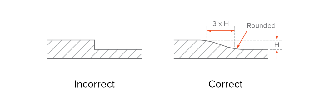
El grosor de la pared uniforme no significa necesariamente que cada pared debe tener exactamente el mismo grosor. Más bien, enfatiza la minimización de grandes variaciones entre las secciones de pared vecinas. En general, el grosor de una pared no debe ser menos del 40% al 60% de las paredes adyacentes. Cuando la variación del grosor es necesaria por razones funcionales o estructurales, las transiciones deben ser graduales, utilizando cementeros o filetes con una longitud al menos 3 veces la diferencia en el grosor, para evitar cambios bruscos en el flujo o el enfriamiento que podrían conducir a la falla de la parte.
Espesor de la pared nominal
El grosor nominal de la pared se refiere al grosor objetivo o promedio de una parte, y sirve como punto de partida para el diseño. Un grosor de la pared adecuado ayuda a garantizar suficiente resistencia a la parte y a reducir los desechos del material. También sienta las bases para el diseño de moho, los parámetros de procesamiento, la configuración del equipo y la selección de materiales.
Las paredes que son demasiado gruesas aumentan el riesgo de contracción y deformación. También requieren más material y tiempos de ciclo más largos, aumentando los costos de producción. Por otro lado, las paredes que son demasiado delgadas pueden solidificarse demasiado rápido o atrapar el aire, lo que lleva a disparos cortos, defectos causados por el relleno de moho incompleto.
Para evitar estos problemas, siempre mantenga el grosor de la pared dentro del rango recomendado para su material elegido. A continuación se muestra una lista de los espesores de pared recomendados para resinas de plástico comunes:
Material
Recomendar el grosor de la pared (en)
Recomendar el grosor de la pared (mm)
Acetal (POM)
0.030–0.120
0.76–3.05
Acrílico (PMMA)
0.025–0.500
0.64–12.70
Acrylonitrilo Butadienestyrene (ABS)
0.045–0.140
1.14–3.56
Nylon (PA)
0.030–0.115
0.76–2.92
Tereftalato de polibutileno (PBT)
0.080-0.250
2.032-6.350
Policarbonato (PC)
0.040–0.150
1.02–3.81
Cetona de éter poliéter (mirada)
0.020-0.200
0.508-5.080
Polietherimida (PEI)
0.080-0.120
2.032-3.048
Polietileno (PE)
0.030–0.200
0.76–5.08
Polifenilsulfone (PPSU)
0.030-0.250
0.762-6.350
Polipropileno (PP)
0.035–0.150
0.89–3.81
Poliestireno (PS)
0.035–0.150
0.89–3.81
Elastómero termoplástico (TPE)
0.025–0.125
0.64–3.18
Poliuretano termoplástico (TPU)
0.025–0.125
0.64–3.18
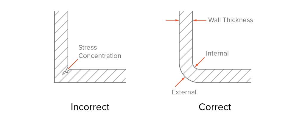
Rincones
Las esquinas afiladas tienden a concentrar el estrés, hacer que el demolte sea más difícil y acelerar el desgaste en la superficie del molde. El material puede acumularse o enfriarse de manera desigual en estas transiciones agudas, lo que resulta en líneas de flujo u otros defectos. Además, las esquinas afiladas a menudo requieren el uso de EDM (mecanizado de descarga eléctrica) para formar el moho, lo que aumenta los costos de herramientas.
La mejor práctica es usar esquinas redondeadas. Las pautas generales de diseño son las siguientes:
▪ Use un radio interno de al menos el 50% del grosor de la pared (mínimo del 25% si el espacio es limitado). ▪ Haga que el radio externo sea igual al radio interno más el grosor de la pared. ▪ Los radios de esquina internos y externos comparten el mismo punto central.
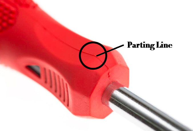
Línea de separación
La línea de separación es la costura formada donde se encuentran las dos mitades del molde. Por lo general, aparece en la superficie de la parte moldeada y es una característica inevitable en el moldeo por inyección. La colocación de la línea de separación afecta la complejidad del moho, la eficiencia de producción y la apariencia final o la funcionalidad de la pieza.
Una idea intuitiva podría ser colocar la línea de separación en la mitad de la parte. Pero esto no siempre es posible, o incluso práctico. En realidad, la línea de separación debe posicionarse estratégicamente para equilibrar el atractivo visual, la función y la complejidad del moho. Por ejemplo:
Ocultar la línea de separación en áreas menos visibles. Un buen ejemplo es el LEGO Brick, donde la línea de separación se oculta sutilmente a lo largo de la parte inferior en lugar de la cara superior, lo que garantiza que las superficies más visibles sigan siendo perfectas.
Evite colocar la línea de separación en áreas funcionales críticas, como superficies de sellado, agujeros de apareamiento o insertos roscados. La presencia de una línea de separación en estas regiones puede causar ligeras variaciones dimensionales, flash o mal ajuste.
Evite colocar la línea de separación en filetes o superficies curvas. Estas características requieren una mayor precisión del moho, lo que aumenta los costos de fabricación y puede conducir a un cierre de moho incompleto, lo que resulta en flash u otros defectos. En su lugar, debe colocar la línea de separación a lo largo de líneas divididas naturales (por ejemplo, bordes afilados, pasos o líneas de interrupción) para simplificar la construcción de moho, mejorar la eficiencia del desmoldeo y reducir los costos de herramientas y mantenimiento.
Para geometrías más complejas, los diseñadores pueden necesitar introducir líneas de separación irregulares o incluso incorporar acciones laterales para acomodar subprote o características ocultas.
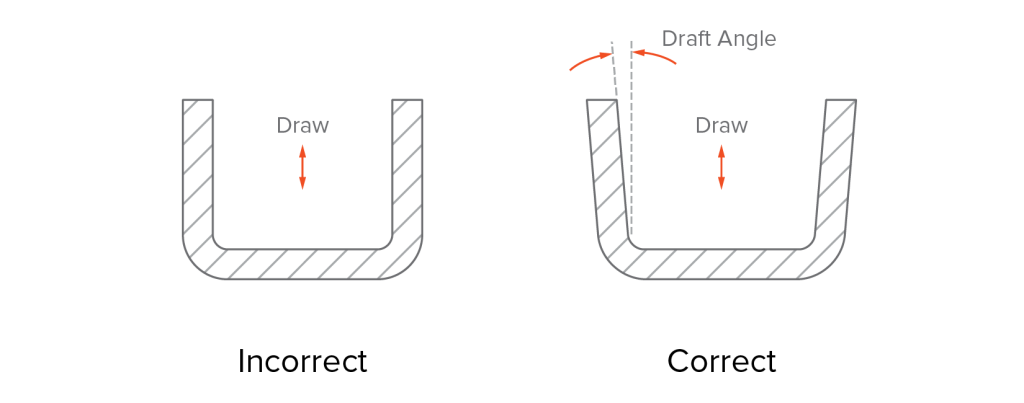
Borrador
El borrador es el ángulo aplicado a las superficies verticales de una parte moldeada por inyección para permitir la expulsión suave del molde. Sin un borrador adecuado, la pieza contactaría firmemente a la superficie del molde, arriesgando la fuerza excesiva durante la expulsión. Esto puede reducir la calidad de la parte, conducir a piezas de chatarra e incluso puede dar lugar a daños a las herramientas.
Muchos programas de software CAD facilitan agregar ángulos de borrador, pero es mejor aplicarlos en las etapas finales del diseño para evitar la complejidad innecesaria. Al determinar el ángulo de borrador apropiado, se deben considerar los siguientes factores:
Material
Diferentes plásticos tienen diferentes características de flujo, que afectan el ángulo de borrador requerido. Materiales como el polipropileno (PP), el polietileno (PE) y el poliestireno (PS) generalmente tienen buenas propiedades de flujo y baja viscosidad. Para estos materiales, un ángulo de borrador de 1 ° a 3 ° es típicamente suficiente. Por el contrario, los plásticos termoestables como el epoxi y las resinas fenólicas a menudo requieren ángulos de borrador más grandes (3 ° o más) para garantizar una expulsión suave.
Acabado superficial
El borrador está relacionado con la textura de la superficie y la suavidad de sus piezas moldeadas por inyección. Los acabados más suaves requieren menos borrador, mientras que las texturas más pesadas requieren más. Por ejemplo:
▪ Para acabado suave, un ángulo de borrador de aproximadamente 1–2 ° es generalmente suficiente. ▪ Para piezas con texturas ligeras o moderadas, generalmente se requiere un ángulo de borrador de 3 a 5 °. ▪ Para texturas pesadas, se necesita un ángulo de borrador de al menos 5 °. ▪ Una regla general de Thumbs debe agregar 1.5 ° de borrador para cada 0.001 "(0.025 mm) de la profundidad de textos) de la profundidad de textos) de la profundidad de textos) de la profundidad de textos.
Durante el moldeo por inyección, la textura del molde se transfiere a la superficie de la pieza. El tipo de producto que está diseñando influirá en su elección de acabado de moho. Organizaciones de la industria como la Sociedad de la Industria de Plastices (SPI) y la Sociedad de Ingenieros Alemanes (VDI), así como compañías como Mold-Tech (MT) y Yick Sang (YS), han establecido clasificaciones estandarizadas para acabados de molde pulidos y texturizados. Estos estándares ayudan a guiar la selección de ángulos de borrador adecuados basados en los requisitos de acabado superficial.
La tabla de acabado superficial a continuación enumera los ángulos de borrador recomendados para los acabados más comunes.
Estándar SPI
Borrador (°)
Textura tecnológica de molde
Borrador(°)
A-1
0.5
MT-11000
1.0
A-2
0.5
MT-11010
1.5
A-3
0.5
MT-11020
2.5
B-1
1.0
MT-11030
3.0
B-2
1.0
VDI Texture-PC
B-3
1.0
VDI-18
1.0
C-1
1.5
VDI-24
1.5
C-2
1.5
VDI-33
3.0
C-3
1.5
Textura de YS
D-1
2.0
YS1XX
1.0
D-2
2.5
Ys3xx
4.0–5.5
D-3
3.0
YS5XX
6.0–12.0
Construcción de moho
Establezca sus ángulos de borrador con la forma en que se abre el molde: la dirección de "dibujar" del molde. De lo contrario, la parte puede atenerse a la mitad que contiene los pasadores del eyector y no se liberará correctamente. Además, asegúrese de aplicar un borrador no solo a todas las paredes verticales sino también a cualquier característica como agujeros o jefes.
Por ejemplo, imagine una parte rectangular con cuatro a través de agujeros. Si los agujeros se redactan hacia la cavidad, la parte puede permanecer atascada allí después de moldear. En cambio, redactarlos hacia el lado central, donde vive el sistema eyector, para que los alfileres puedan expulsar la pieza limpiamente.
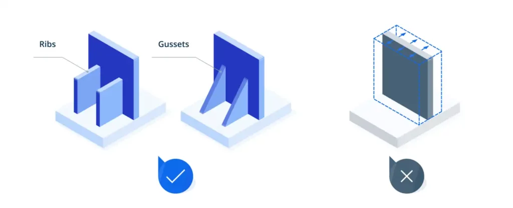
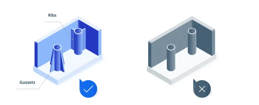
Costillas y escudetes
Las costillas y los refuerzos se usan para reforzar las estructuras localizadas y mejorar la rigidez de las piezas sin aumentar el grosor general de la pared.
Costillas
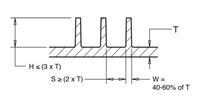
Las costillas son delgadas, como las protuberancias de la pared que se extienden desde la superficie de una parte, a menudo en áreas anchas y delgadas de paredes o características en forma de caja, para distribuir cargas de manera uniforme y mejorar la rigidez general. Para garantizar un diseño efectivo de costillas, siga estas mejores prácticas:
▪ El grosor de la costilla debe ser del 40 al 60% del grosor principal de la pared. ▪ La altura de la costilla no debe exceder tres veces el grosor de la pared. ▪ Aplicar un ángulo de borrador de 0.5 ° –1 ° para ayudar a la liberación del molde. ▪ Agregue un filete en la base de la costilla con un radio de 0.25–0.5 × el grosor de la pared. ▪ ▪ ■ ■ oll a cada cuatro veces el espesor de las cuatro veces el espesor de la costa de la costa de las cuatro veces. Costillas, jefes o bordes de agujeros) para proporcionar una sala de enfriamiento adicional y evitar puntos calientes.
Buneses
Los buneses son placas triangulares o trapezoidales pequeñas colocadas en la unión de paredes, jefes o costillas para fortalecer los puntos de estrés altos locales. Las mejores prácticas para el diseño del escenario incluyen:
▪ El refuerzo generalmente debe ser de aproximadamente un tercio a la mitad tan gruesa como la pared que soporta. ▪ Una corbata nunca debe ser más alta que el jefe o la costilla que está reforzando. De hecho, a menudo solo necesita que el Gusset sea alrededor del 30-50% de la altura de ese jefe, lo cual es suficiente para brindar apoyo en la mayoría de los casos. ▪ Aplicar un borrador de 0.5 ° a 1 ° para garantizar una expulsión suave. ▪ Use filetes generosos en la base del ceño para reducir la concentración de estrés y mejorar el flujo de plástico; Un radio de 0.25 a 0.5 veces el grosor de la pared es generalmente apropiado. ▪ Coloque los escondidas simétricamente cuando se usa en pares y evite el hacinamiento. ▪ Mantenga un espacio de al menos 2 a 3 veces el grosor del escudo de características adyacentes para garantizar un enfriamiento uniforme y evitar defectos de moldeo.
Jefe
Los jefes son características cilíndricas diseñadas para recibir inserciones, tornillos de autocomprobación o alfileres para el ensamblaje o el montaje. También se puede ver como costillas circulares que contribuyen a la resistencia estructural general. Se deben evitar los jefes independientes. Conéctese siempre a paredes o superficies adyacentes usando costillas o espondas en lugar de estar completamente integradas en la pared misma.
Al diseñar jefes, recuerde lo siguiente:
▪ Coloque a los jefes donde se necesita integridad estructural o resistencia a la fijación, como en las ubicaciones de los tornillos. ▪ Para los tornillos de auto -tocado, tamaño el jefe OD a aproximadamente 2–2.5 × el diámetro principal del tornillo. ▪ Limite el grosor de la pared del jefe a ≤60% de la pared adjunta para evitar el hundimiento o las anoches. El diámetro del orificio ligeramente para compensar la contracción plástica y garantizar un ajuste adecuado después del moldeo.
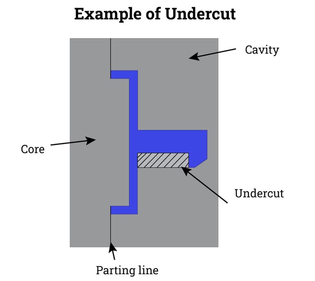
Subvenciones
Las características subterráneas o sobresalientes que crean un enclavamiento entre la pieza y una o ambas mitades de moho, evitando la expulsión limpia a lo largo de la dirección de apertura del molde. Los ejemplos comunes incluyen ganchos, ajustes, agujeros, ranuras y ranuras laterales que son perpendiculares o transversales a la dirección de separación del molde.
Si bien los subcortes a veces son necesarios para la función mecánica o el ajuste de ensamblaje, generalmente requieren herramientas adicionales, como núcleos deslizantes, levantadores o cámaras, que aumentan la complejidad del moho, el tiempo del ciclo y el costo de fabricación. Los socavos de diseño incorrecto pueden causar dificultades de expulsión, distorsión de la pieza, desgaste excesivo o falla de la herramienta.
Algunas pautas de diseño para los subcortes son las siguientes:
▪ Los eventos de los eventos siempre que sea posible modificando la geometría, reor elastómeros). Evite PP/PE a menos que la altura del recorto sea ≤0.3 mm con paredes muy delgadas. Provide a 30°–45° lead in chamfer and add 0.5°–1° draft on the bump off face to ensure smooth ejection. ▪ If undercuts are necessary, keep them minimal, localized, and placed on a single side to reduce the need for multiple side actions. ▪ Incorporate proper draft angles (typically ≥1°) and generous radii around undercut features to ease ejection and reduce stress on both the part and the mold.
Texto y símbolos
El texto y los símbolos (por ejemplo, números de pieza, logotipos, marcas de reciclaje) están comúnmente en relieve o debilitan en piezas moldeadas para la trazabilidad, la marca o el cumplimiento regulatorio. Aquí hay algunos consejos útiles:
▪ Use el texto elevado (en relieve) en lugar del empotrado (grabado) cuando sea posible, ya que el texto grabado requiere herramientas de molde más complejas, acelera el uso de la herramienta y aumenta el costo, especialmente para altos volúmenes o diseños intrincados. flujo de plástico, y reduzca el desgaste de la herramienta. ▪ Use un espesor de carrera uniforme y un tamaño de fuente mínimo de 20 puntos (aproximadamente 7 mm de altura). ▪ Evite colocar el texto cerca de las paredes delgadas, las esquinas afiladas, las costillas o las superficies de alta cosmética, ya que estas áreas son más propensas a las marcas, las marcas de fregadero, o los problemas de eyección. ▪ ■ »■» ■ »■» ■ »■» de orientación de orientación a las superficies de los moldes para el régimen de régimen de régimen o de la línea de régimen de muelles. Simplifique el mecanizado y evite la distorsión durante la expulsión.
Tolerancias
La tolerancia al moldeo por inyección define la desviación permitida de las dimensiones de una parte de su diseño nominal. En el diseño, se deben aplicar tolerancias más estrictas a las características críticas, como las interfaces de ensamblaje, las ranuras de sellado y la ubicación de los agujeros, ya que estos impactan directamente el ajuste y la funcionalidad. Para las dimensiones no críticas, como el ancho de las superficies no con carga, se pueden utilizar tolerancias más flexibles para reducir los costos de fabricación.
Hay dos niveles de tolerancia comunes:
Tolerancias comerciales:Relativamente flojo (típicamente ± 0.1 mm o ± 0.004 "), y funcionan bien para la mayoría de las características no críticas a un costo menor.
Bien tolerancias:Más apretado (típicamente ± 0.05 mm o ± 0.002 "), requerido para piezas de alta precisión, con mayores costos de herramientas y fabricación.
Durante el diseño, las tolerancias dimensionales deben ajustarse de acuerdo con la contracción del material. Diferentes plásticos tienen diferentes tasas de contracción: materiales cristalinos semi (por ejemplo, PA, PP, PE, POM) se encogen más que los materiales amorfos (por ejemplo, ABS, PC, PMMA). Aunque la contracción es generalmente predecible, las ligeras variaciones en la formulación de resina o las condiciones de procesamiento (como la temperatura de fusión) pueden influir en el tamaño final de la pieza. A medida que aumenta el tamaño de la parte, la variación de contracción se vuelve más pronunciada. Dependiendo del material, debe esperar una tolerancia relacionada con la contracción de aproximadamente ± 0.002in/in (0.05 mm/mm).
El análisis de pilas de tolerancia también debe considerarse en ensambles de múltiples piezas, porque incluso si cada característica individual (por ejemplo, un agujero) está dentro de su tolerancia especificada, la variación acumulativa puede conducir a la desalineación, especialmente cuando múltiples agujeros a través de diferentes partes deben alinearse para que los sujetadores pasen.
Tenga en cuenta que las tolerancias de moho también influyen en la calidad de la parte final. Las tolerancias de mecanizado de moho estándar son de alrededor de ± 0.005 "(0.13 mm), pero se pueden requerir tolerancias más estrictas para piezas de alta precisión. Además, los moldes experimentan el desgaste con el tiempo, lo que puede conducir a una deriva dimensional. Es importante planificar el mantenimiento de las herramientas y la renovación para mantener una calidad de pieza consistente durante las carreras de producción a largo plazo.
Conceptos básicos de diseño de moldes
El diseño de piezas y el diseño de moho están estrechamente vinculados para determinar el éxito de un producto moldeado por inyección. A medida que el diseño de la parte se centra en la geometría y la funcionalidad, el diseño de moho traduce esos requisitos en una herramienta fabricable. La siguiente sección describe los aspectos fundamentales del diseño de moho:
Base de moho y diseño de cavidad
Las herramientas de moho consisten en una base estándar de moho, cavidad e insertos de núcleo, y cualquier componente móvil (portaobjetos, levantadores, placas de eyectores, etc.). La base del molde proporciona el marco rígido (soporte de pilares guía, placas de soporte y el sistema de eyección) mientras que la cavidad y los insertos del núcleo definen la forma de la pieza. Juntos, controlan cómo se moldea de precisión y consistente cada parte.
Un buen diseño de moho debería:
▪ Use una base estándar (por ejemplo, DME o HASCO) para un abastecimiento rentable y un fácil reemplazo de los componentes desgastados. ▪ Mantener el grosor de la placa adecuado y guiar el tamaño del pilar para resistir la presión de inyección y garantizar la alineación. Para mantener la temperatura uniforme y minimizar la deformación o la variación de contracción. ▪ Incluya un espacio de borrador y expulsión adecuados para que las piezas se liberen limpiamente y los tiempos de ciclo se mantengan cortos. ▪ Para nuevos productos, un solo molde de cavidad es a menudo la forma más rápida y rentable de validar el diseño. Una vez que se finaliza el diseño, puede mudarse a múltiples cavidades o moldes familiares para ampliar la producción.
Puertas
Las puertas son los puntos de entrada a través de los cuales el plástico fundido fluye hacia la cavidad del moho. Su tamaño, forma y colocación tienen un gran impacto en la apariencia parcial, la resistencia estructural y la presencia de defectos de moldeo, como marcas de flujo y líneas de soldadura.
▪ Las piezas más grandes necesitan puertas más grandes para mantener la presión y la velocidad de flujo para el llenado completo. ▪ Posiciar las puertas en la sección más gruesa de la pieza para promover el relleno uniforme, la contracción de control y minimizar los defectos. ▪ Coloque las puertas de baja tensión, áreas de baja visibilidad siempre que sea posible, ya que los vestigios pequeños y pueden debilitar la parte. ▪ Usar múltiples gates en grandes o complejos en las áreas de balance y evitar el flujo de balance en el flujo de balanza pequeñas. Las puertas dejan un pequeño vestigio, los ubican en la línea de separación para un fácil recorte y una visibilidad mínima.
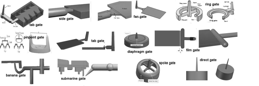
Las puertas se pueden clasificar mediante el método de recorte, manual o automático, y ciertos tipos son más adecuados para geometrías de piezas específicas. La imagen a continuación muestra los ejemplos comunes de las puertas.
Tipos de puerta manual
▪EDGE GATE (puerta estándar):Sección transversal rectangular a lo largo de la línea de separación; ideal para piezas planas o rectangulares; Se puede reducir para un mejor flujo. ▪Puerta del ventilador:Abertura ancha y acampanada para piezas de paredes grandes o delgadas; Minimiza el corte y mejora el saldo de llenado. ▪PABA DE PAB:Variante de la puerta de borde con una pequeña pestaña para absorber la cizalladura y el calor; adecuado para materiales sensibles al corte. ▪Puerta de diafragma:Puerta circular alrededor del núcleo para el flujo concéntrico; Excelente equilibrio pero difícil y costoso de recortar. ▪Puerta de anillo:Anillo continuo alrededor del núcleo para incluso relleno radial; usado en piezas en forma de tubo. ▪Puerta de voz:Variante de puerta de anillo con costillas radiales; Bueno para las partes tubulares simétricas, pero mantener la concentricidad es un desafío. ▪Puerta de película (flash):Puerta muy delgada y ancha para piezas grandes/delgadas; Asegura un relleno uniforme pero deja un vestigio largo que necesita recorte manual.
Tipos de compuerta automáticamente
▪Puerta submarina (túnel):Entrada en ángulo debajo de la línea de separación; Descansos automáticos durante la expulsión para una mancha mínima. ▪Puerta de precisión:Puerta pequeña y directa dentro de la línea de separación; ideal para materiales de alto flujo y piezas cosméticas; común en moldes de cavidades múltiples o precisión.
Sistema corredor
El sistema de corredores guía el plástico fundido desde el rociado hasta las puertas y hacia las cavidades del moho. El diseño del corredor afecta el flujo de material, el tiempo del ciclo y la calidad de la parte, especialmente en los moldes de múltiples cavidades o familiares. Un sistema de corredor eficiente asegura que el plástico fundido fluya uniformemente a todas las cavidades. El flujo equilibrado previene defectos como la variación dimensional, los disparos cortos y las líneas de soldadura. La distribución desigual también puede causar sobrecalentamiento localizado o un reclamo insuficiente, lo que afecta tanto la resistencia como el acabado superficial.
La forma y el tamaño del canal del corredor impactan directamente el comportamiento del flujo y la eficiencia del procesamiento. Los corredores de ronda completa reducen la pérdida de presión, pero aumentan la complejidad de las herramientas, mientras que los corredores trapezoidales o semicirculares son más fáciles de mecanizar pero menos eficientes. Los corredores de gran tamaño desechan material y enfriamiento lento; Los de menor tamaño restringen el flujo y pueden causar un relleno incompleto. En los moldes de múltiples cavidades, los corredores deben ser simétricos y distribuirse de manera uniforme para garantizar que cada cavidad se llene simultáneamente.
Hay dos tipos principales de sistemas de corredores:
Corredores fríosson más simples y rentables, pero generan un exceso de material (chatarra de corredor) que deben eliminarse o reciclarse.
Corredores calientesElimine este desperdicio y ofrezca un mejor control sobre el flujo y la temperatura, pero requieren un mayor costo de herramientas y esfuerzo de mantenimiento.
El sistema de corredores debe estar diseñado en coordinación con la puerta y los sistemas de enfriamiento. Un diseño bien optimizado reduce el tiempo de ciclo, mejora la consistencia y admite un moldeo eficiente y de alta calidad.
Alfileres de eyectores
Los pasadores de eyectores se usan para sacar la parte moldeada de la cavidad una vez que se ha solidificado. Su colocación y diseño afectan significativamente la calidad de la parte, la eficiencia de expulsión y la vida útil del moho. Las recomendaciones de diseño son:
▪ Coloque los pasadores del eyector en superficies no subméticas, como cerca de la línea de separación. ▪ Evite colocar pines en áreas de paredes delgadas o en ángulo que puedan deformarse bajo la fuerza de eyección. ▪ Localizar pines en las áreas mecánicamente fuertes de la parte de la pie Los pasadores para extender la carga y evitar la deformación. ▪ El número y el tipo de pines dependen de factores como la geometría de la pieza, los ángulos de borrador y el grosor de la pared. Por ejemplo, las piezas con puertas de borde o ventilador pueden necesitar pines adicionales para la eyección equilibrada. ▪ Los pasadores de eyectores deben estar hechos de materiales de alta resistencia y resistentes al desgaste para garantizar la durabilidad a largo plazo.
Sistema de enfriamiento
El sistema de enfriamiento mantiene la temperatura del molde para controlar la contracción, el tiempo de ciclo y la calidad final de la parte. Los canales deben enrutarse para un enfriamiento uniforme, con un espacio más apretado (3–5 mm de la cavidad) alrededor de las secciones gruesas. Asegúrese de que las líneas de enfriamiento no entren en conflicto con las puertas, corredores o hardware de eyección. El diámetro de canal adecuado (típicamente 6-10 mm) y los colectores equilibrados mejoran aún más la consistencia térmica y acortan los tiempos del ciclo.
Trabajar con Chiggo para obtener comentarios de DFM expertos y prototipos
Ahora que tiene una comprensión más clara de cómo el diseño de moldeo por inyección afecta la fabricación, el rendimiento y el costo, es hora de avanzar. Una vez que su diseño está listo, Chiggo ofrece un análisis DFM gratuito (diseño para fabricación) junto con su solicitud de cotización. Este análisis ayuda a identificar posibles problemas o riesgos relacionados con la fabricación de moho y el moldeo por inyección.
¿Qué sigue? Creando unprototipopuede ayudar a validar sus decisiones de diseño antes de que comience las herramientas.Chiggo está aquíPara guiarlo a través de cada paso del viaje de moldeo por inyección, asegurando una transición suave del diseño al producción.