Lathe cutting tools are specialized instruments mounted on lathe machines— whether manual, woodworking, or CNC— to shape, cut, or finish rotating workpieces. These tools typically consist of a shank fixed to the lathe tool post and a cutting edge that directly engages with the workpiece. Available in various shapes, sizes, and materials, they can perform a range of operations such as turning, facing, threading, and parting when combined with different tool paths.
Choosing the right tool determines the precision and efficiency of your work. In this article, we will discuss common lathe cutting tools, explore their designs and features, and help you select the right one for your project.
Understanding Different Types of Lathe Cutting Tools
When discussing the types of lathe cutting tools, there are various classification methods. Whether it is based on operational requirements, tool geometry, materials, or feed direction, the goal is the same: to recognize the lathe cutting tools and clarify what they can do.
Despite the wide variety of lathe cutting tools, let's set aside complex classification systems for now. Instead, we’ll focus on understanding the tools right in front of us—what they look like and what they can achieve. If we can answer those two questions, we’ll be well on our way to mastering their usage.
What do they look like?
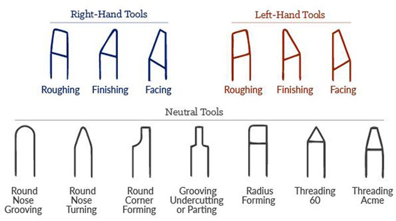
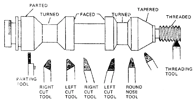
The images above showcase the three major types of lathe cutting tools based on feed direction. The differences among these three types are clearly visible. Next, we will provide a detailed introduction to the appearance and functions of each tool, helping you better understand their uses.
▪ Right-Hand Cutting Tools
Right-hand cutting tools have their main cutting edge on the left side and are designed to cut as they move from right to left, toward the headstock. Since most lathe operations feed the tool in this direction, these are the most commonly used in lathe work. They are typically employed for general turning tasks such as reducing workpiece diameter, facing ends, and achieving smooth surface finishes.
▪ Left-Hand Cutting Tools
Opposite to the right-hand version, the left-hand cutting tools have their main cutting edge on the right side and cut as they move from left to right, away from the headstock. These tools are particularly useful for machining operations near the tailstock or when obstructions on the left side of the workpiece require feeding the tool in the opposite direction.
▪ Neutral Cutting Tools
Neutral cutting tools have a symmetrically positioned cutting edge along the tool’s centerline, allowing them to cut in both directions without needing to change orientation. They are commonly used for finishing operations or applications where consistent cutting performance is required in both feed directions. However, they are less frequently used in heavy-duty or specialized tasks compared to right-hand or left-hand tools.
What operations can they achieve?
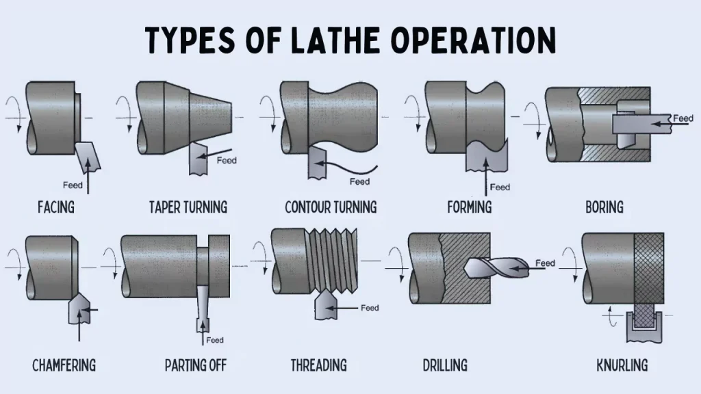
Now that we understand the basic geometry, let’s explore what operations these tools are designed to perform. Lathe cutting tools are engineered to meet specific requirements in various lathe operations, and their design reflects the functionality they are meant to achieve.
▪ Turning Tools
Turning tools are the most widely used lathe cutting tools, designed to remove material along the length of a workpiece to reduce its diameter. This category includes roughing tools for removing large amounts of material and finishing tools for making precise, fine cuts.
▪ Facing Tools
Facing tools cut perpendicularly to the axis of rotation, creating a flat, smooth surface on the end of the workpiece. This facing operation is often performed to prepare the workpiece for subsequent machining processes, such as drilling or threading, or to finish the end of a part to precise dimensions.
▪ Parting Tools (Cut-Off)
Parting tools typically have a thin, straight blade with a sharp cutting edge. They are typically used to cut through the diameter of a rotating workpiece, separating one portion from the rest. In addition to their primary function, these tools can also be used to create grooves in the workpiece when necessary.
▪ Chamfering Tools
Chamfering tools are used to cut a beveled edge, typically at a 45-degree angle, on the edges of a workpiece. This operation is often performed to remove sharp edges for safety or aesthetics, to prepare the workpiece for further machining (such as threading), or to ensure proper fit during assembly.
▪ Threading Tools
Thread cutting tools are used on lathes to cut helical threads. The nose angle of the tool determines the thread shape, such as V-threads or square threads. These tools are typically categorized into external and internal thread cutting tools. External thread cutting tools cut threads on the outer surface of a workpiece, like bolts or screws. Internal thread cutting tools are used to create threads inside a hole, as seen in nuts or threaded bores.
▪ Grooving Tools
Grooving tools are designed to cut narrow grooves on the surface of a workpiece. These grooves can be external, for applications like shaft shoulders or retaining ring grooves, or internal, within a hole or bore, for features such as internal snap rings. Additionally, grooving tools can be used on the end face of a workpiece to create grooves perpendicular to the axis of rotation, commonly for face seal applications.
▪ Knurling Tools
Knurling tools are another type of lathe cutting tool used to create a textured pattern on the workpiece’s surface, typically for improved grip or decorative purposes. Unlike other cutting tools, knurling tools do not remove material. Instead, they use pressure to impress straight or diamond patterns into the surface.
Additional Cutting Tools
The tools below are not traditional lathe cutting tools, but they are lathe-compatible tools that often perform specific operations on a lathe:
▪ Drilling Tools
Drilling tools create holes along the center axis of a rotating workpiece. A drill bit is mounted in the lathe’s tailstock and fed into the workpiece as it rotates. Drilling is often the first step before more precise internal machining operations, such as boring or tapping.
▪ Boring Tools
Boring tools are used to increase the size of an existing hole in the workpiece. These tools are typically designed as single-point tools, with the primary purpose of enlarging and correcting the hole's diameter.
▪ Reaming Tools
Reaming involves using a multi-edged tool to finish a pre-drilled or pre-bored hole, improving both the dimensional accuracy and surface finish. Reamers don't significantly change the hole's size but fine-tune it for greater precision.
▪ Tapping Tools
Unlike threading tools, tapping tools are used to cut internal threads directly in a pre-drilled hole in one operation. A tap creates threads that allow screws or bolts to be inserted. It is best for fast, high-production threading of smaller holes, where speed is more important than fine control.
Important Supplements About Tool Materials
Lathe cutting tools are crafted from materials that are largely similar to those of milling cutter tools. For example, high-speed steel (HSS), carbide, ceramic, and cubic boron nitride (CBN) are commonly used. These materials are widely applied in both turning and milling tools due to their excellent hardness, wear resistance, and heat resistance.
Notably, diamond tools are also used in lathe cutting. This is mainly because turning is a continuous cutting process, and the high hardness and wear resistance of diamond tools are well-suited for this type of operation. In contrast, milling involves intermittent cutting with higher impact loads, which makes the cutting conditions unsuitable for diamond tools. Therefore, diamond tools are preferably used in lathe operations but rarely in milling.
Components of A Lathe Cutting Tool
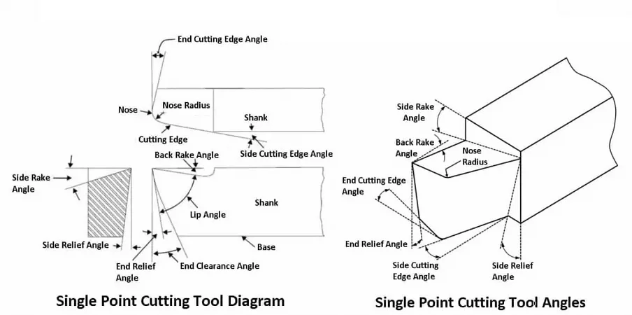
Although there are many different types of lathe cutting tools, they almost all consist of several key components, each influencing how the tool interacts with the workpiece during the cutting process. Now, let's take the single point cutting tool as an example to delve into the details of these elements.
Shank: The main body of the cutting tool that is clamped into the lathe’s tool holder. It secures the tool in place and transmits cutting forces while providing structural support.
Cutting Edge: The cutting edge is the sharpened part of the tool that directly interacts with the workpiece to remove material through shearing action. In single-point cutting tools, it consists of the side cutting edge and the end cutting edge, forming the primary point of material removal. The cutting edge can be an integral part of the tool or a replaceable insert made from materials like high-speed steel (HSS), carbide, or ceramic, affecting the tool's performance and suitability for different applications.
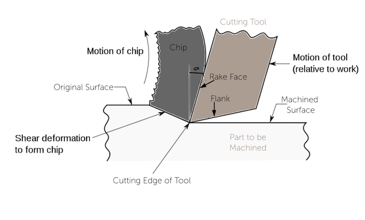
Rake Face: The rake face is the surface of a cutting tool that is in direct contact with the material being cut. It is responsible for guiding the chip away from the workpiece during machining and plays a critical role in determining the cutting efficiency, chip formation, and tool wear. The angle of the rake face, known as the rake angle, can significantly affect cutting forces and the quality of the machined surface.
Flank: The flank of a cutting tool is the surface opposite the rake face that faces the newly machined surface and does not make direct contact with the material being cut. It is responsible for providing clearance to prevent friction between the tool and the workpiece, thereby reducing tool wear and ensuring smooth cutting without interference. The flank has two components: the side flank and the end flank. The side flank is adjacent to the side cutting edge, while the end flank is adjacent to the end cutting edge. The angle between each flank and the workpiece, known as the side relief angle and end relief angle respectively, helps maintain proper clearance during cutting operations, preventing rubbing and prolonging tool life.
Tool Nose: The tool nose is the rounded tip where the side cutting edge and end cutting edge meet. The nose radius affects the surface finish and strength of the cutting edge, with a larger radius enhancing finish but reducing sharpness.
Side Rake Angle: The side rake angle is the angle between the rake face and a horizontal plane parallel to the workpiece surface. It influences how the chip flows away from the cutting zone during machining. A positive side rake angle reduces cutting forces and helps improve chip removal, while a negative or zero side rake angle can increase cutting forces but may provide greater strength to the cutting edge.
Back Rake Angle: The back rake angle is the angle between the rake face and a horizontal plane parallel to the workpiece surface, measured along the main cutting edge. It affects the cutting forces and chip flow, influencing how easily the tool can cut into the material. Adjusting the back rake angle is crucial for optimizing tool performance based on the material being machined.
Side Relief Angle: The side relief angle is the angle between the flank and a vertical plane perpendicular to the workpiece surface, measured along the tool’s side cutting edge. It provides clearance to prevent friction and rubbing between the tool’s side and the workpiece during side-cutting operations, ensuring smoother cutting and reduced tool wear. A properly set side relief angle helps to reduce tool wear, improves cutting performance, and ensures a smooth finish on the workpiece. If the angle is too small, it may cause rubbing, while an overly large angle can weaken the cutting edge.
End Relief Angle: In contrast, the end relief angle is the angle between the flank and a plane perpendicular to the workpiece surface, measured along the tool’s end cutting edge. This angle provides clearance to prevent friction and rubbing between the tool’s end and the workpiece during end-cutting operations. It enhances cutting efficiency and improves surface finish. A too-small end relief angle can lead to excessive friction and heat, while a too-large angle may weaken the cutting edge.
End Cutting Edge Angle: The end cutting edge angle is the angle between the tool's end cutting edge and a line perpendicular to the workpiece surface. It influences chip flow direction and cutting forces. A larger angle reduces cutting forces and improves chip flow, enhancing tool life but may increase deflection. A smaller angle strengthens the cutting edge but can raise cutting forces and wear.
Side Cutting Edge Angle: The side cutting edge angle is the angle between the tool’s side cutting edge and a line parallel to the workpiece surface. It influences cutting force direction, chip formation, tool strength, and surface finish. A larger angle spreads the cutting load, reducing forces and improving surface finish, but may weaken the edge. A smaller angle concentrates cutting forces, potentially increasing wear but enhancing material removal in some cases.
Tips for Selecting the Right Lathe Cutting Tool
Selecting the right lathe cutting tool requires careful consideration of many factors, such as the specific machining operation, tool geometry, material of both the tool and workpiece,and cutting conditions . Here are some practical tips to help you make an informed decision:
1. Align the tool choice with the lathe operation you're performing. For example, turning tools are used to remove material along the length of a workpiece; however, they are not suitable for forming operations. Other considerations include the cutting direction.
2. Consider the workpiece and tool material. The mechanical properties of the workpiece, particularly its hardness, will influence your selection of tool material. For softer materials like aluminum, high-speed steel (HSS) tools may suffice. For harder materials like stainless steel or hardened alloys, carbide or ceramic tools are more appropriate. The cutting edge material must withstand the mechanical stresses and thermal conditions generated during machining. When necessary, opt for coatings that enhance tool life and performance. Coatings like TiN (Titanium Nitride) or TiAlN (Titanium Aluminum Nitride) can provide increased hardness and wear resistance.
3. Tool geometry also plays a significant role. The rake and relief angles must be suited to the operation and workpiece material to minimize friction and wear while ensuring proper chip formation and evacuation. For example, a high back rake angle improves chip flow in softer materials, while a more neutral angle may be needed for harder materials to reduce tool wear.
4. Cutting speed, feed rate, and depth of cut should also influence your selection. Tools designed for high-speed applications, like carbide or ceramic tools, can handle faster cutting speeds without degrading. Meanwhile, if your operations involve a slower feed rate or shallow cuts, a tool with a smaller nose radius or a higher rake angle might improve finish quality.
5. Lastly, factor in cost and tool life. While high-performance tools like carbide and diamond can be more expensive upfront, their durability and ability to handle a wider range of materials and cutting conditions may reduce downtime and tool changes in the long run, making them more cost-effective for heavy production use.
Conclusion
Lathe cutting tools are indispensable for achieving precision and efficiency across various machining operations. Understanding the different tool types, their components, and how they align with specific lathe operations allows for better decision-making in tool selection. Whether you're turning, facing, threading, or boring, the right tool will significantly impact the quality, speed, and cost-effectiveness of your project.
At Chiggo, our expert engineers are here to assist you in selecting the best lathe cutting tools for your CNC turning projects. From rapid prototypes to on-demand machined parts, we deliver high-quality solutions tailored to your needs. Simply upload your CAD files today to get an instant quote and a free DFM analysis.