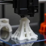
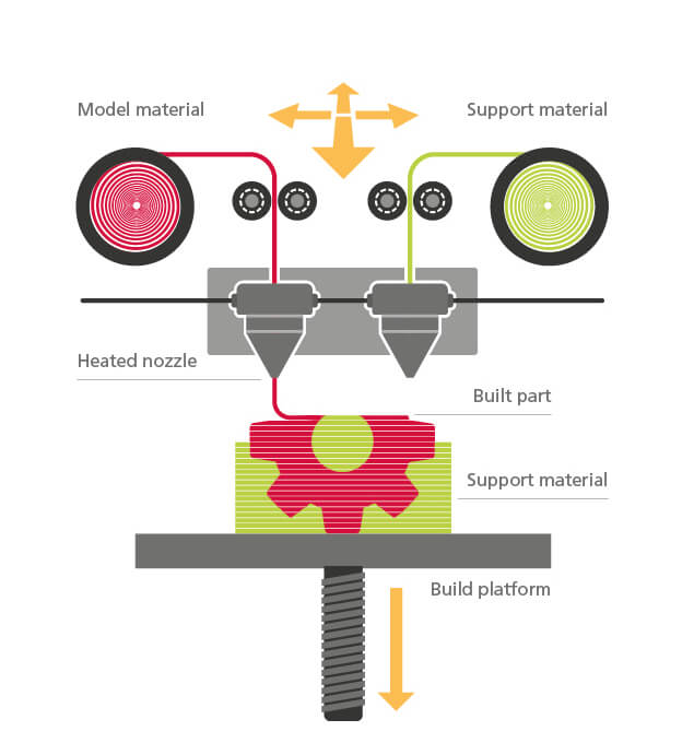
Fused Deposition Modeling (FDM) is a material-extrusion 3D printing process . It works by feeding a thermoplastic filament into a heated nozzle, where it melts and is deposited layer by layer along a programmed toolpath to build the part. In essence, an FDM printer works much like a computer-controlled hot glue gun, extruding thin beads of molten plastic that quickly solidify to form a three-dimensional object.
FDM is the most widely used 3D printing method, particularly at the consumer and educational level. With the largest installed base of printers worldwide, it is often the first process people think of when talking about 3D printing. You may also see the term Fused Filament Fabrication (FFF) used interchangeably. Because “FDM” is a trademark owned by Stratasys, the open-source 3D printing community adopted “FFF” as a neutral alternative; in practice, both terms describe the same extrusion-based process.
This article explains the basics of FDM, including its pros and cons and the differences between desktop and industrial machines. It also covers the common printing plastics and the situations where FDM is most suitable.
A Brief History of FDM
While FDM is now the most popular 3D printing method, it was not the first to be invented. In fact, it came after both stereolithography (SLA) and selective laser sintering (SLS). Scott Crump filed the first FDM patent in 1989—three years after SLA and one year after SLS—and together with his wife Lisa founded Stratasys to bring the technology to market.
Throughout the 1990s, Stratasys held the key patents and positioned FDM primarily for industrial prototyping. A major shift came in 2005 with the RepRap (Replicating Rapid Prototyper) Project, an open-source initiative by Adrian Bowyer that aimed to create self-replicating printers. When the core FDM patents expired in 2009, this movement paved the way for companies such as MakerBot, Ultimaker, and Prusa Research to emerge, making desktop printers affordable for hobbyists and educators.
By the 2010s, industrial systems from Stratasys and consumer printers from companies inspired by the open-source movement together had firmly established FDM as the world’s most widely used 3D printing technology.
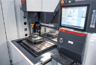
Desktop vs. Industrial FDM Printers
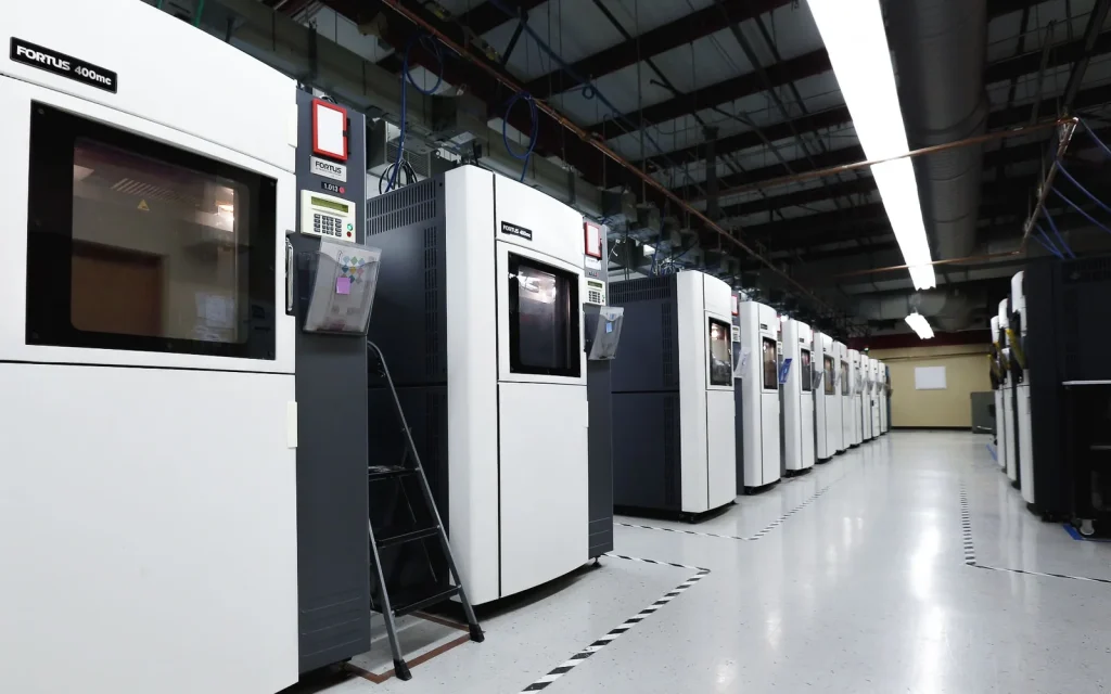
Today, this evolution has resulted in two main categories of machines: industrial systems for professional production and desktop printers for consumers and educators. Their key differences are summarized below:
Property
Industrial FDM
Desktop FDM
Standard accuracy
Around ±0.2–0.3 mm
Around ±0.2–0.5 mm
Typical layer thickness
0.15–0.3 mm
0.1–0.25 mm
Minimum wall thickness
~1 mm
~0.8–1 mm
Maximum build volume
Large (e.g., 900 × 600 × 900 mm)
Medium (e.g., 200 × 200 × 200 mm)
Common materials
ABS/ASA, PC, Nylon, ULTEM
PLA, ABS, PETG, TPU
Support materials
Breakaway & soluble
Same material or soluble (dual-extruder)
Production capability
Low–medium; repeatable batches
Low; prototypes and one-offs
Machine cost
$50,000+
$500–$5,000
How FDM Works: Step-by-Step Process
An FDM printer turns a digital design into a physical object through the following steps:
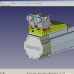
3D Modeling : The process begins with a digital model, usually created in CAD software or downloaded from a 3D library. The model is exported in a format like STL or OBJ, which defines the object’s geometry.
Slicing: Slicing software converts the 3D model into a stack of two-dimensional layers and generates the toolpaths the printer will follow. It also adds any necessary supports for overhangs and outputs a G-code file containing the print instructions. Key settings,such as layer height, print speed, infill density, and support placement, are chosen at this stage and directly affect print quality and duration.
Printer Setup: The filament spool is loaded into the extruder, which feeds material toward the hot end. The build plate is cleaned and leveled to ensure proper adhesion of the first layer, and for materials like ABS, it is typically preheated to reduce warping.
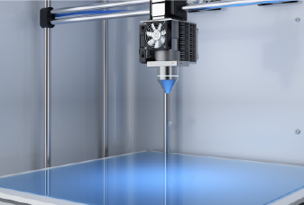
Heating, Extrusion, and Layer Deposition: When the nozzle reaches the target temperature, the extruder pushes filament into the heated head, where it melts. The extrusion head is mounted on a three-axis motion system (X, Y, Z) that guides the nozzle precisely across the build area. As the head moves, it extrudes thin strands of molten plastic onto the build plate along the predetermined path.
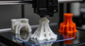
Each new layer is deposited on top of the previous one. The material cools and solidifies quickly; in many cases, cooling fans attached near the extrusion head accelerate this process, especially for materials like PLA. To fill in wider regions, the nozzle makes multiple passes until the layer is complete. Then, either the build platform descends or the extrusion head rises by one layer height, and the machine begins the next layer. This cycle repeats hundreds or thousands of times until the entire part is built.
The material cools and solidifies almost immediately—often aided by fans for faster cooling with materials like PLA. To fill an area, the nozzle makes multiple passes, much like coloring in a shape with a marker. Once a layer is complete, either the build platform lowers or the extrusion head rises by one layer height, and the process repeats. Layer by layer, the part is built up from the bottom until it is fully formed.
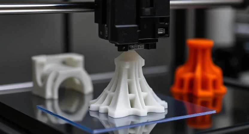
Support Structures: For overhangs or bridges, the printer generates support material to keep unsupported sections from collapsing. These supports may be printed in the same plastic and later broken off, or in a secondary dissolvable filament if the printer has multiple nozzles.
Post-Processing: Once the final layer is deposited, the part cools and is removed from the build plate. Most FDM prints require little more than support removal, but additional finishing steps can be applied if a smoother surface or enhanced performance is desired.
Common post-processing methods for FDM parts include:
Sanding and polishing – smooths visible layer lines and prepares surfaces for painting.
Priming and painting – adds color and improves surface aesthetics.
Cold welding – uses solvents (such as acetone for ABS) or adhesives to bond parts together or seal seams.
Vapor smoothing – exposes the part to solvent vapors, melting the outer surface slightly to produce a glossy finish.
Epoxy coating – applies a thin resin layer that fills in gaps, improves strength, and can make parts watertight.
Metal plating – adds a metallic surface layer for durability, conductivity, or visual effect.
Advantages and Disadvantages of FDM
Pros
Cost-Effective
FDM is generally the most affordable 3D printing method in both machine price and material cost. Desktop units range from just a few hundred to a few thousand dollars, and even many industrial FDM systems remain less expensive than their SLA or SLS counterparts. Filament is inexpensive, widely available in many brands and types, and easy to source. This low barrier to entry makes FDM accessible for classrooms, research labs, and small businesses.
Rapid Prototyping Speed
FDM is excellent for fast design iteration. A part can be printed in minutes to a few hours, allowing teams to go from concept to physical prototype overnight. Compared with methods that require long curing or cooling cycles, FDM shortens lead times and accelerates product development.
Wide Material Selection
FDM supports a broad range of thermoplastics, from common and affordable options like PLA, ABS, and PETG to engineering-grade materials such as Nylon, Polycarbonate, and TPU, and even high-performance polymers like ULTEM or PEEK on industrial systems. This versatility allows engineers to choose materials that closely match the performance requirements of the final product.
Scalability (Print Size)
Unlike resin or powder-based systems, which are restricted by vat or bed dimensions, FDM machines can be scaled simply by enlarging the frame and motion system. This scalability gives FDM a clear cost-to-size advantage and makes it a practical solution for producing large prototypes such as automotive components or architectural models.
Ease of Use and Simple Post-Processing
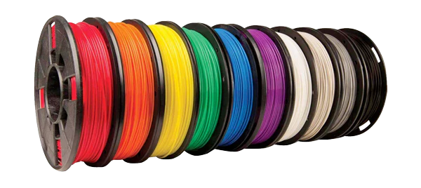
Operating an FDM printer is straightforward: load the filament, start the print, and remove the part when it’s done. Post-processing is usually limited to detaching supports, unlike resin printing which requires washing, curing, and handling of chemicals. Many FDM parts are ready to use immediately, with extra finishing only required for certain materials or applications. Another advantage is color flexibility: with filaments available in a wide range of shades, models can often be printed in their final look without the extra painting that resin prints typically require.
Design Flexibility in Strength and Material Use
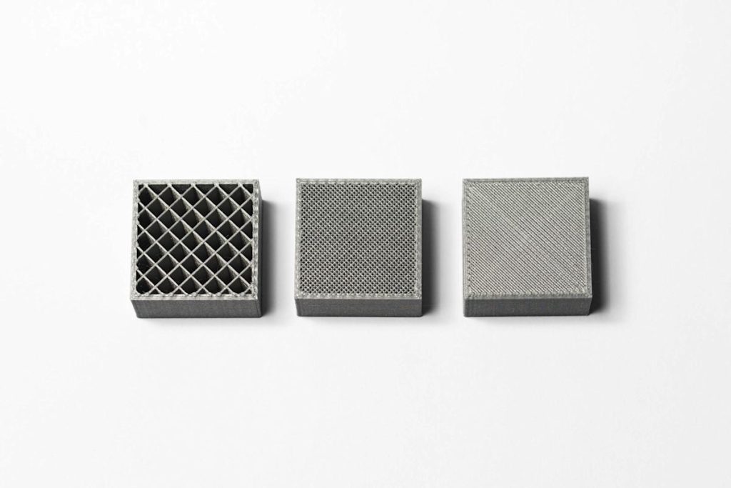
FDM allows users to adjust infill density and shell thickness, balancing print time, material consumption, and mechanical performance. This tunability means parts can be optimized as lightweight prototypes or as stronger functional components. On higher-end systems, dissolvable support materials are also available, making it easier to handle complex geometries and simplifying post-processing.
Less Material Wastage
FDM uses filament that is melted and deposited exactly where needed, so almost no raw material is wasted during printing. This contrasts with powder-based methods like SLS or MJF, where unused powder requires handling and may degrade after multiple cycles. With smart design that minimizes or eliminates support structures, FDM can be even more efficient in material usage.
Cons
Limited Resolution & Surface Finish
FDM builds objects with visible layer lines, and even at fine settings (~0.1–0.2 mm), curved surfaces show a “stair-stepping” effect. The minimum feature size is limited by nozzle diameter (often ~0.4 mm), so very small details or precision fits are difficult to achieve. As a result, professional-quality appearance or accuracy often requires post-processing: threads may need tapping, holes may need reaming, and surfaces may need sanding, painting, or vapor smoothing for a polished finish. FDM also struggles to produce fully watertight or airtight parts without additional sealing.
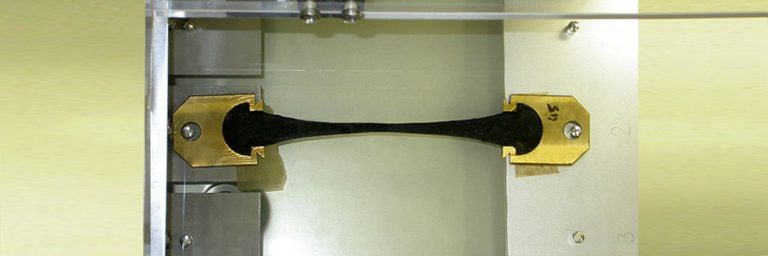
Anisotropy and Layer Adhesion Issues
Because parts are made layer by layer, FDM prints are anisotropic: significantly weaker along the Z-axis. The bonding between layers is less robust than within a layer, making parts more likely to split or delaminate under stress applied perpendicular to the build direction. This limits their performance in mechanically critical applications unless part orientation and infill are carefully optimized.
Warping and Accuracy Challenges
Thermal contraction during cooling can cause parts to warp, with edges lifting off the build plate or thin features bending. ABS and Nylon are especially prone to this, often requiring heated beds or enclosed chambers. Even with calibration, achieving high dimensional accuracy is difficult, with tolerances typically around ±0.1–0.3 mm. Holes and fine details often need adjustment or machining for a precise fit.
Support and Geometry Constraints
FDM printers require support structures for overhangs steeper than ~45° or long bridges. These supports add material, extend print times, and can leave blemishes when removed. Complex internal geometries may be impossible to print because supports would be trapped inside. While dual-extruder machines with dissolvable supports improve flexibility, they add cost and still require removal steps.
Material Limitations
Although FDM supports many thermoplastics, it is still limited to that class of materials. Metals and full ceramics cannot be printed directly. High-performance polymers like PEEK or ULTEM require very high nozzle and chamber temperatures, making them accessible only on specialized industrial machines. As a result, each FDM printer can only handle a subset of the full material spectrum.
Calibration and Maintenance Demands
Due to the simplicity and cost-driven design of FDM systems, users often spend time tweaking settings like bed leveling and nozzle height to achieve consistent quality. The heavy reliance on mechanical motion means regular maintenance is needed—adjusting belt tension, lubricating rails, cleaning extruders, and replacing parts such as nozzles or hot ends.
Feedstock Sensitivity
Print quality is highly dependent on filament quality. Poor dimensional tolerance in filament diameter or inconsistent composition can lead to extrusion problems. In addition, most filaments are hygroscopic; if not stored properly, they absorb moisture from the air, leading to bubbling, poor surface finish, or weak layer adhesion during printing.
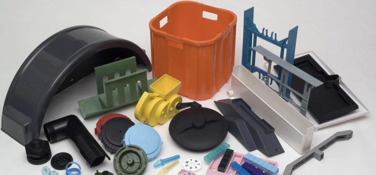
Common Materials Used in FDM Printing
Decades of development in the plastics industry have created a wide range of polymer filaments, from everyday plastics to specialized engineering polymers.
PLA is the most popular filament for desktop FDM printers. It’s a biodegradable plastic (often corn-starch based) that is easy to print and produces parts with good detail and surface quality. When higher toughness and temperature resistance are needed, ABS is usually the choice. However, ABS is more prone to warping and often requires a heated bed or chamber to keep corners from lifting.
Another popular alternative is PETG, which combines PLA’s ease of printing with ABS’s durability. It offers a good balance of strength, flexibility, and chemical resistance.
Industrial FDM machines, on the other hand, mainly use engineering thermoplastics such as ABS, polycarbonate (PC), and Ultem (PEI). These materials often include additives to enhance their properties, making them suitable for demanding applications that require high impact strength, thermal stability, chemical resistance, or even biocompatibility.
The table below summarizes the key pros, cons, and typical applications of the most common FDM printing materials:
Material
Pros
Cons
Common Applications
PLA
Easy to print; great detail & surface finish. Bio-based and minimal warping.
Brittle; low heat resistance (deforms at ~60 °C). Not ideal for load-bearing parts.
High-performance: great strength-to-weight, flame retardant, works up to ~170 °C. Used in aerospace, automotive.
Very expensive material; only prints on high-end machines due to extreme temperature requirements.
Aerospace parts, under-the-hood automotive components, medical devices
When to Use FDM
Given the strengths and limitations discussed, here are some typical cases where FDM is the most suitable choice compared to other methods:
Cost or Speed is the Primary Concern: If you need a prototype quickly and inexpensively, FDM is hard to beat. You can go from CAD to a physical part in the same day without breaking the bank. Perfect for early-stage prototyping, student projects, and hobby builds where affordable iteration matters more than perfection.
The Part Size is Large: Large-format FDM printers can handle parts that would be extremely costly or impossible in resin vats or powder beds. Think architectural models, full-size casings, or big functional prototypes – FDM scales up more easily and at lower cost.
Functional Prototypes in Real Plastics: When you need the prototype to behave like a production plastic part – for example, a clip that must flex without breaking or a mount that must withstand heat – FDM with ABS, PC, or Nylon is ideal. These parts can be drilled, screwed, and tested in working conditions where resin prints might fail.
Custom Tools, Jigs, or Replacement Parts: FDM excels at producing one-off or low-volume parts tailored to specific needs. A custom jig for assembly? A replacement knob for equipment? Print it overnight and put it to work. For many moderate-duty uses, FDM prints can serve as real end-use parts.
Educational and Home Environments: FDM is the most user-friendly and safe 3D printing option in classrooms, makerspaces, and homes. PLA and similar filaments are easy to handle, letting learners focus on design and engineering. The low cost per part also encourages experimentation and iteration.
When Post-Processing Must Be Minimal: If you need a part straight off the printer with little extra work, FDM fits. Just remove supports, and the part is ready to handle. For demos and workshops, this immediacy makes FDM especially practical.
Chiggo’s FDM 3D Printing Services
Chiggo offers on-demand FDM 3D printing for both prototypes and production runs. We can deliver high-quality FDM parts in just a few days. Upload your CAD files to receive an instant quote. For more details or to discuss your requirements with our team, contact us today.