金属3D打印正在迅速发展 - 更快地建立速度,更好的材料性能和更广泛的应用领域。本指南将向您展示如何充分利用金属添加剂制造(AM):我们将讨论金属3D打印技术的主要类型,常见材料以及所有费用。我们还将比较金属AM与减法(CNC加工 )和形成性(金属铸造)方法,因此您可以选择适合您的部分,预算和时间表的正确过程。
什么是金属3D打印?
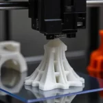
类似于所有其他3D打印过程(例如聚合物3D打印),Metal 3D打印机通过基于数字3D设计的一次添加材料来构建零件,因此添加了添加剂制造。仅此一次,该过程使用金属粉末,电线或聚合物结合丝而不是塑料。
这样,可以使用传统方法制造的几何形状来构建零件,而无需使用诸如模具或切割工具之类的专业工具。同样重要的是,增加的几何复杂性对构建成本几乎没有影响,因此有机,拓扑优化的结构是实用的。最终的零件更轻(通常减轻了25%–50%的重量),并且通常更硬,这对于航空航天和其他高性能领域至关重要。
这种设计自由还可以使组件合并:多个组件,其所有紧固件,关节和泄漏路径都可以成为一次单一的印刷部分,可以立即执行多个功能。劳动力下降,交货时间缩小和维护更为简单,因为组装,对齐或服务较少。也就是说,与许多传统方法相比,金属3D打印仍然很昂贵,并且尚未在较高量的单位成本上竞争。
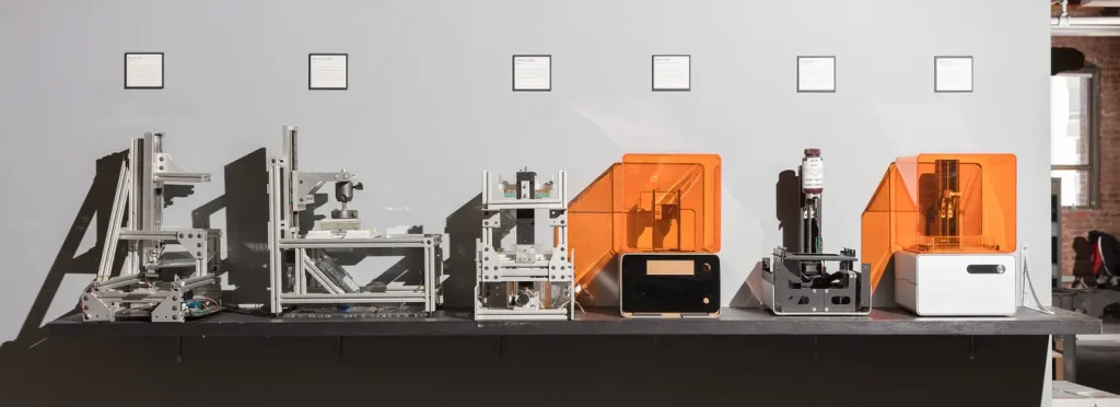
金属3D打印的简短历史
在1980年代后期,德克萨斯大学的卡尔·德卡德(Carl Deckard)博士开发了第一个激光烧结3D打印机,该打印机最初是为塑料设计的。这项技术成为选择性激光烧结(SLS)的基础,这种方法后来将扩展到金属3D打印。
1991年,MIT的Ely Sachs博士引入了一个3D打印过程,现在称为Binder Jetting。这种金属粘合剂喷射方法于1995年获得了授权。
1995年,德国的Fraunhofer研究所提交了第一项用于金属激光熔化的专利,该专利为当今的金属3D打印方法奠定了选择性激光融化(SLM)的基础。在此期间,EOS和各种大学等公司在进一步开发该技术方面发挥了关键作用。
由于设备和材料的高成本,金属3D打印在2000年代初期生长缓慢。但是,大约在2012年,随着SLM,DMLS和EBM等关键技术的专利开始到期,许可费下降了,为新竞争对手打开了大门。这一转变引发了创新,并吸引了GE,HP和DMG Mori等公司的重大投资,从而降低了成本并加速了各个行业的采用。
今天,根据优先研究报告 ,全球金属3D打印市场在2024年的价值为96.6亿美元,预计将从2025年的120.4亿美元增长到2034年的873.3亿美元,复合年增长率为24.63%。市场是由对快速原型制作,定制和复杂组件的需求以及航空航天和汽车部门不断增长的。
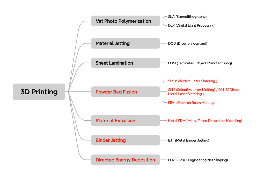
金属3D打印技术的类型
市场上有许多金属3D打印技术,但最广泛使用的四种是粉末床融合(PBF),粘合剂喷射,金属融合沉积建模(金属FDM)和有向能量沉积(DED)。从广义上讲,它们属于两种机制:融化和烧结。
PBF和DED融化金属原料(粉末或电线),具有高能源,如激光器,电子束或弧,可产生接近完全致密的部分。相比之下,金属FDM和活页夹首先用聚合物粘合剂创建了一个“绿色”部分,然后将其在熔点下方搅拌并烧结。最终密度通常低于完全融化的过程,并且几乎总是需要额外的后处理。
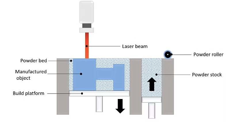
粉床融合(PBF)
粉末床融合(PBF)被广泛认为是最常用的金属3D印刷家族。其中,选择性激光熔化(SLM) 和直接金属激光烧结(DML) 已经使用了20多年了,是当今技术上最成熟的金属3D打印过程,其次是电子束熔化(EBM) ,另一种关键方法,特别是用于航空航天和医疗应用中的钛合金。
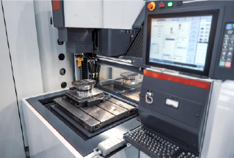
PBF工艺首先预热构建室,该室首先充满了惰性气体,达到最佳温度。然后,一层薄层的金属粉末散布在整个构建平台上。激光(在SLM和DML中)或电子束(在EBM中)针对粉末床,根据零件的设计有选择地熔化或融合粉末颗粒。颗粒融合在一起形成第一层,然后将平台稍微降低。一层新的粉末散布在上一个粉末上,然后按一层重复该过程,直到零件完全构建为止。
由于构建温度很高(许多合金通常> 1000°C),因此通常需要支撑以将零件固定到位并防止热应力扭曲。冷却后,去除多余的未倒粉(刷,爆炸或吸尘),并通过切割或切除支撑电线EDM。 然后对该零件进行热处理以减轻残余应力并增强材料特性。最后,根据要求,该零件可能需要其他完成,例如CNC加工,抛光 或其他表面处理,以达到所需的表面质量和尺寸精度。
常见粉末床融合方法的特征
这是三个主要PBF金属3D打印技术的详细比较表:
财产 选择性激光熔化(SLM) 直接金属激光烧结(DML) 电子束熔化(EBM) 能源 激光 激光 电子束 使用的材料 球形金属粉末具有单个熔化温度;包括铝合金,钛,不锈钢,工具钢和某些合金 带有变化熔点的球形金属粉末;包括不锈钢,钛合金,镍合金,贵金属和工具钢 球形金属粉末,例如钛合金,钴铬合金,镍超合金和其他高性能材料 过程 激光完全融化粉末以形成致密的零件 激光烧结(融化粉末,但没有完全液化) 电子束在真空环境中融化粉末 构建体积 通常小到中等(通过机器而变化) 通常小到中等(通过机器而变化) 与SLM/DML相比,通常可用的构建量更大 建立速度 中等(取决于激光功率和部分复杂性) 中等(随材料和零件大小而变化) 较慢(由于使用电子束和真空环境) 印刷零件属性 内部孔隙率小于0.2-0.5%;高密度和出色的机械强度 该部分性质类似于SLM,但由于烧结过程,轻微的孔隙率可能更明显 孔隙率通常很低,但由于构建速度较慢和过程中较大的层厚度,它可能比SLM略高 维度的准确性 ±0.1 mm ±0.1 mm ±0.1 mm 典型的构建尺寸 250 x 150 x 150毫米 250 x 150 x 150毫米 500 x 500 x 380毫米或更大 常见的层厚度 20-50μm 20-50μm 50-150μm 支持 总是需要 总是需要 总是需要 典型的表面粗糙度 RA8-10μm RA8-10μm RA20-60μm 每部分费用 $$$$$ $$$$$ $$$$$$ 关键应用程序 具有高几何复杂性(有机,拓扑优化结构)的零件需要出色的材料特性,以提高苛刻应用的效率 类似于SLM 需要强,弹性零件的高性能应用,尤其是在航空航天和医疗植入物中,需要钛合金和其他高强度材料
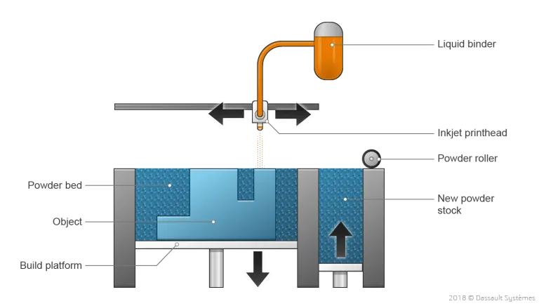
活页夹喷射
粘合剂喷射最初用于创建砂岩的全彩色原型和型号。随着时间的流逝,它在制造金属零件方面越来越受欢迎,尤其是由于其批处理生产能力。在金属粘合剂喷射过程中,一层金属粉末散布在整个平台上。然后,配备有喷墨喷嘴的马车然后通过粉末床,沉积结合剂的液滴(通常是聚合物和蜡的混合物),以将金属颗粒粘合在一起。一层层完成后,构建平台就会向下移动,并应用了新的粉末层。此过程重复直到整个部分构建。
金属粘合剂射流中的打印步骤发生在室温下,消除了诸如扭曲和内部应力之类的问题,这些问题可能会在DML和SLM等过程中发生。不需要支持结构。但是,印刷部分保持“绿色”状态,这意味着它仍然脆弱,需要进一步处理。
有两个常见的后处理步骤用于将“绿色”部分转化为完全固体的金属组件:
浸润: 去除粘合剂后,该部分被认为是“棕色”,并且具有明显的内部孔隙度(约70%)。然后将“棕色”部分加热在具有低熔点金属(通常是青铜)的工业烤箱中,该烤箱填充了内部空隙,从而产生了BI金属部分。尽管这种方法可以提高强度,但今天的使用量较少,因为它的材料特性仍然不如完全烧结的零件,其机械性能和热性能没有得到充分的文献记载。
烧结: 现在,首选的后处理,“绿色”部分放在炉子中,其中粘合剂被燃烧,金属粉末颗粒将其融合在一起,成完全致密的成分。该零件在烧结过程中通常会收缩约20%,因此零件打印稍大以补偿。
金属粘合剂喷射的特性
财产 金属粘合剂喷射 使用的材料 目前仅限于不锈钢(例如316L,17 4PH),工具钢(例如H13),青铜/铜合金和Inconel 625 建立速度 在所有金属3D打印技术中最快的;床通常密集地包装有许多小零件 印刷零件属性 烧结后〜1–2%残留孔隙度;拉伸强度与铸造金属相当,但由于内部空隙,疲劳寿命显着较低 维度的准确性 ±0.2 mm(试验后±0.1) 典型的构建尺寸 250×175×200mm(高达400×300×200mm) 常见的层厚度 早期系统运行35–50µm,高吞吐量系统高达100µm) 支持 不需要 典型的表面粗糙度 Ra10–15µm作为烧结的零件 每部分费用 $$$(更快的构建,没有支持废物) 关键应用程序 低至中等的功能原型和复杂组件,其中吞吐量和单位成本比最大的机械性能重要
金属融合沉积建模(金属FDM)
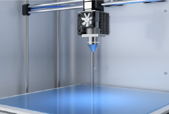
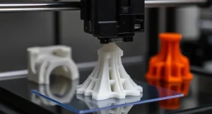
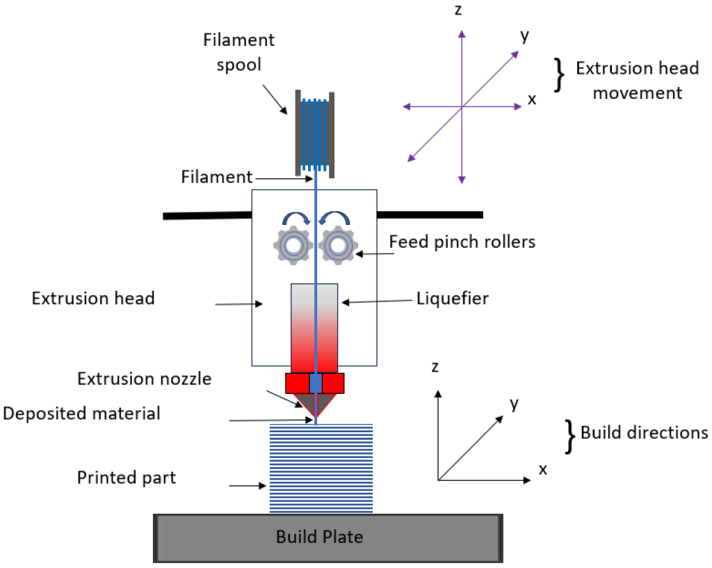
金属挤出是塑料经典FDM过程的一种变体,但它使用了通常由聚合物和/或蜡结合在一起的金属颗粒组成的金属丝或杆,而是使用金属丝或棒,因此有时被称为细丝材料挤出。
该杆或细丝通过加热的喷嘴挤出,并逐层沉积,以基于CAD模型构建零件。同时,如有必要,建立支持结构。支撑与零件之间的接口用陶瓷支撑材料打印,以后易于手动删除。需要后处理所得的“绿色”部分,以使用类似(但不相同)的粘合剂喷射的步骤成为金属。首先将“绿色”部分浸泡或热处理,以去除大多数聚合物/蜡粘合剂(脱落),然后在炉子中烧结,因此金属颗粒将其融合成密集的,完全金属的碎片。在烧结过程中,零件在每个方向上缩小了大约15-20%,因此CAD模型会提前缩放,并且可能需要进行一些试验调整。
金属融合沉积建模的特性
财产 金属融合沉积建模 使用的材料 目前非常局限于316L,17 4PH,H13,铜/青铜合金和Inconel 625 建立速度 缓和;比粘合剂喷射慢,但是设置/迭代比SLM便宜,更简单 印刷零件属性 密度〜90–97%(髋关节最高〜98%);拉伸强度大致含量/铸件,通常比锻造低20-40%;残余孔隙率降低疲劳强度 维度的准确性 典型±0.30mm;调音和收缩补偿后可实现的±0.15–0.20mm 典型的构建尺寸 250×220×200mm 常见的层厚度 100–200µm 支持 必需的 典型的表面粗糙度 RA 10–20µm在烧结的表面上 每部分费用 $$(低机/材料成本) 关键应用程序 功能性金属原型,自定义工具和一个关闭/低容量零件,成本和简单性比峰值性能更重要
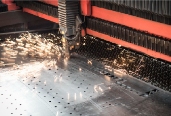
定向能量沉积(DED)
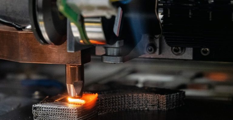
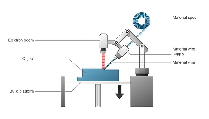
定向能量沉积(DED)使用聚焦的热源,通常是激光,电子束或电/等离子体弧,在工件上创建一个熔体池,而金属粉末或电线被送入其中,用珠子用珠子进行建筑物材料珠。因为打印头可以自由移动(通常在多轴见或机器人上),并且不受粉末床的限制,因此DED非常适合修复或添加现有零件的功能,并产生大型的,近乎净形状的组件。贸易折扣是粗珠几何形状,粗糙的表面,粗糙的表面,粗糙的热量输入以及可以介绍驻留率的大量热量,因此通常需要居住式且均需进行热处理,以达到最终的良好的态度和固定量。
定向能量沉积的特征(DED)
财产 定向能量沉积 能源 聚焦激光,电子束或电/等离子体电弧 使用的材料 与SLM相似的合金系列;标准焊接电线和许多可焊接粉可用 建立速度 与(或以下)粘合剂喷射相媲美 印刷零件属性 〜95–99%的密度(电线进料通常高于粉末);焊接具有定向性能的微观结构;适当的热处理后,拉伸强度可以接近锻造 维度的准确性 典型±0.5–1.0mm 典型的构建尺寸 通常是四个中最大的 常见的层厚度 0.3–1.5mm(电线)或0.2-0.8mm(粉末),具体取决于喷嘴和电源 支持 通常不需要;通过路径计划或临时固定装置处理的悬垂 典型的表面粗糙度 RA> 20–40µm 每部分费用 $$ - $$$(设备昂贵,但高沉积率降低了大零件/维修的成本) 关键应用程序 维修/翻新,功能添加,大结构组件,靠近净形空白,用于随后的加工
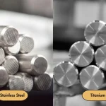
金属3D打印的材料
尽管使用不锈钢,钛和铝合金等广泛使用的工程金属可用于金属3D打印,但在常规制造中使用的许多其他高性能或定制合金仍然很难为AM提供或资格供应AM。由于可打印的粉末通常被气体雾化为球形,尺寸狭窄且氧气低,因此制造成本很高,可提供较少的合金,并且仍然以相对较低的产量生产。也就是说,可用于金属3D打印的金属数量正在迅速增长。今天,工程师可以从包括基于镍的铬铬系统在内的合金中进行选择,这些材料众所周知,这些物质很难在传统上进行机加工。
以下是一些普通AM金属的例子,其中不锈钢,钛和铝仍然是最广泛使用的:
不锈钢
工具钢
钛合金
铝合金
基于镍的超级合金
钴铬合金
基于铜的合金
贵金属(黄金,银,铂等)
异国情调的金属(钯,塔塔勒等)
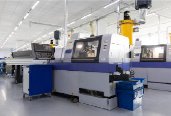
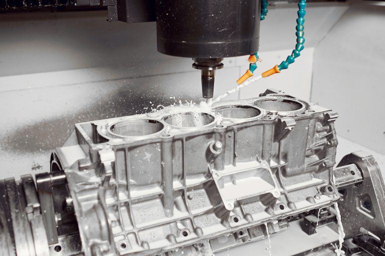
金属3D打印与传统制造业
当您只需要一些复杂的高性能金属零件时,基于工具的方法会缓慢且昂贵。金属3D打印避免使用工具,并使复杂的几何形状直接。对于简单的设计或大量,CNC加工或铸造通常更便宜,更快。以下是金属3D打印与跨关键方面的减法(CNC加工)和形成性(铸造)过程的概述。
方面 金属3D打印 CNC加工 金属铸造 设计自由 非常适合复杂/内部频道,晶格,零件合并 受工具访问和切割器几何形状限制 适合有机外部形状,但需要草稿/核心以及与完全封闭的频道的斗争 工具 /设置 没有模具或切割工具;仅切片/支持设置 没有模具,但是需要进行固定和凸轮编程 需要模具/模具/核心;高前期时间和成本 交货时间(原型) 几个小时 - 周 天(编程 +加工) 几周 - 几个月(工具构建) 单位成本与数量 平坦/高度;高音量缩放很差 随着音量的增加而减小,但每个部分仍然需要机器时间。 高体积非常低;工具后出色的规模经济经济 维度的准确性 缓和;收缩/热效应,过程依赖性(PBF的±0.1-0.3mm)。 高的; ±0.01–0.05mm在精确特征上常见 缓和; ±0.1-0.5mm典型(投资<砂) 表面饰面(原始) 粗糙(RA〜5–20+µm);经常需要完成 良好 - 外观 公平 - 豪华;通常需要加工/抛光 机械性能 在适当的HT/HIP之后,可以接近锻造力量,但由于孔隙率和表面,疲劳通常会降低;推荐压力缓解/臀部 使用锻炼→可预测的高机械性能 铸造微观结构;拉伸和疲劳特性通常低于锻造,但可以通过热处理(有时是髋关节)改善 零件大小 受构建室的限制(DED除外) 受机器信封的限制;存在大型磨坊 非常大的零件可行(沙子铸造,投资铸造) 材料范围 增长但合格的合金较少 几乎所有可加工的金属 非常广泛;大多数合金可铸造,尽管有些很难 废物 /材料效率 低的;未使用的粉末经常回收 高芯片废物(除非单独回收) 中等废物(门控/立管废料) 后处理 支持去除,热处理,髋关节,加工耐受性 毛刺,可能的热处理,完成 训练,热处理,加工到最终公差 最好的用例 复杂,低体积,高价值零件;快速迭代;内部频道/格子 耐受性紧密,体积中等的精密零件 大量或非常大的零件可以摊销工具成本
选择金属印刷而不是传统制造业
1。几何驱动性能
内部通道,晶格填充,保形冷却路径和合并,一块组件很难或不可能加工或铸造。
2。低量
如果您仅需要1-50个零件,例如原型,飞行员运行或备件,则基于工具的方法很少会得到回报。添加剂制造避免了模具和模具,以使单位成本相对平稳且合理。
3。快速设计迭代
只需更新CAD文件,重新切片和打印 - 没有新的固定装置或模具即可。可以对CNC进行重新编程,但通常仍然需要固定/工具更改,而铸造几乎总是需要新的或修改的工具。
4。交货时间比单位成本更重要
通常可以在几天内打印复杂的金属零件,比建造和证明铸造工具所需的6-8周更快。对于AOG(地面上的飞机)情况或紧急工具,速度每件价格胜过。
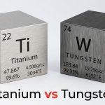
5。难以机械合金
Inconel,Co CR和其他超级合金的剪裁昂贵:它们很艰难,快速工作并破坏工具。金属3D打印跳过最切割,避免了工具磨损和热量问题。 SLM或EBM等高能量过程甚至可以从超高熔点金属(例如钨(3422°C))中构建组件,这些金属几乎无法有效地机加工。
6。最小化材料废物(购买比率)
传统的加工可以废除80-90%的航空航天坯料。使用粉末床AM,大多数未使用的粉末可以被过滤和重复使用,因此您更接近净形状。例如,钛托可能只需要〜1.2×最终质量而不是〜6倍。
7。按需或现场生产
您使用它们的备件slashes库存和物流。离岸钻机可以在现场打印一个自定义不锈钢阀门,而不是等待数周的加工替换。
8。维修或添加现有零件的功能
定向能量沉积重建磨损的涡轮刀片或将老板添加到昂贵的住房中。沉积后,CNC完成恢复了精确的轮廓,通常比整个部分再制造便宜。
9。拓扑优化和轻巧
我可以让您实现有机,优化的几何形状,以消除非负载轴承质量。用晶格填充物重新设计的航空航天铰链可以在保持强度的同时减轻40%的重量,结果对磨坊或铸造不切实际。
10。组装合并
打印一个集成的部分,而不是加工,然后将许多作品固定在一起。例如,具有多个泄漏路径的12件液压歧管可以成为带有内部通道的单个印刷块。这意味着更少的紧固件,较少的接头,更少的装配时间和更高的可靠性。
11。定制或分级材料
在不同区域需要利基合金或不同的特性吗?某些AM系统(尤其是DED)可以在构建过程中切换粉末或电线以创建组成梯度。研究团队打印具有较软区域的Ti – NB植入物,用于骨骼整合和较硬的负载轴承,这都是一方面的。
金属3D打印的成本
金属3D打印通常比塑料更昂贵,因为在三个方面的成本要高:设备,材料和后加工操作。以下各节详细讨论了每个部分。
设备成本
金属打印机要复杂得多:高功率激光器或电子梁,惰性气体或真空室,多激光扫描系统,精密光学元件和受控粉末输送 - 都比FDM或光聚合机机器更昂贵。典型的价格范围是技术:
SLM / DML(激光粉床融合):$ 300,000– $ 2,000,000+
定向能源沉积(DED):$ 200,000- $ 1,000,000+
金属活页夹喷射(打印机加上DEBIND/SINTER单元):$ 300,000- $ 800,000+
金属FDM /细丝材料挤出(打印机加上DEBIND / SINTER单位):$ 100,000- $ 200,000
材料成本
金属3D打印材料的成本也比典型的塑料高。在金属原料中,雾化粉末是最昂贵的,因为它必须以高球体,狭窄的颗粒大小范围和非常低的氧气含量产生。 DED的电线通常比粉末便宜,而聚合物结合的金属丝(用于金属FDM中)仍然更便宜。
雾化粉(SLM,粘合剂喷射):大约$ 100– $ 600,具体取决于合金(低端不锈钢,高端Ti/ni)
电线(DED):大约$ 20– $ 80;粉末食用DED更接近粉末床价格
聚合物结合的金属丝(金属FDM):大约$ 50– $ 150
后处理
支撑清除,缓解压力周期,髋关节,CNC饰面和表面处理可以增加每个构建或每个零件的数百甚至数千美元。活页夹喷射和金属FDM还需要脱丝和烧结,这增加了炉子的时间和成本。
下表是典型的DMLS/SLM成本贡献者的细分。请注意,后处理如何占总数的很大份额。
生产步骤 手术 典型的成本* 制造业 金属粉 $ 200–每公斤500美元(材料依赖) 机器时间(一个构建板) $ 2,000- $ 4,000 后处理 压力缓解周期 $ 500– $ 600 零件/支持删除 $ 100– $ 200 热处理 /臀部 $ 500– $ 2,500 CNC加工 $ 500– $ 2,000 表面精加工 /涂料 $ 200– $ 500
*实际数字随几何形状,批量尺寸,材料,区域以及商店如何分配开销而变化。根据零件尺寸,单个构建板可以容纳1-12个零件(或更多)。
此外,易消耗的惰性气体,炉子和激光功率,粉末筛分和测试,灰尘爆炸/氧化安全措施以及持续的维护和校准都使金属3D打印的运行成本显着高于塑料印刷品。
结论
金属3D打印的潜力远远超出了当今的航空航天和医疗用途。随着越来越多的合金,更智能的机器和更轻松的后处理上网,许多领域的公司将使用它来验证现实世界的性能并削减定制,复杂的金属零件的成本。如果您正在考虑通过Metal AM扩展功能,取得联系 . Our team can help you decide when and how it makes sense.