この記事では、一般的な間違いを軽減し、製品の品質を向上させ、高価な金型の変更と再加工を避けることでコストを削減するのに役立つ射出成形のための実用的なデザインのヒントを提供します。
射出成形の概要
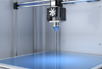
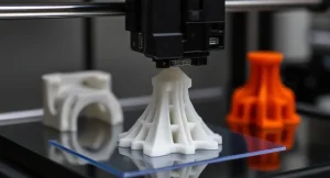
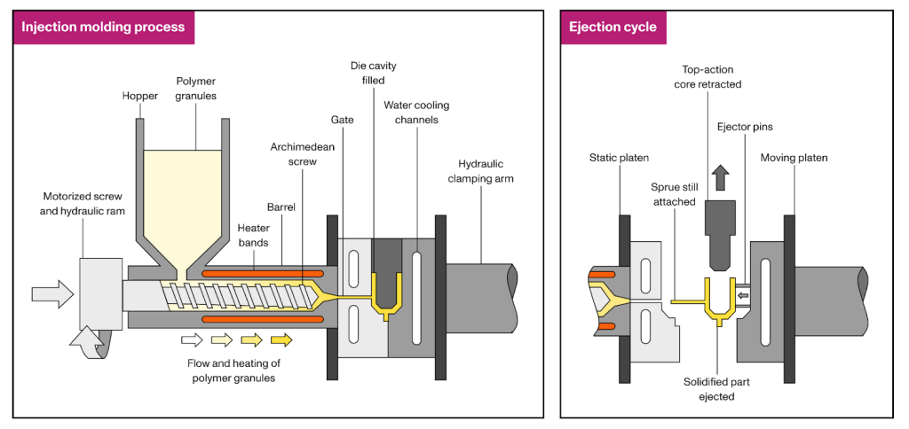
射出成形は、最も費用対効果の高いものの1つです製造プロセス 同一のプラスチック部品を大量に生産するため。このプロセスでは、ポリマーペレットを最初に溶かし、次に圧力下で型に注入します。プラスチックが冷えて固化すると、型が開き、部品が排出されます。その後、サイズはパーツサイズとカビの複雑さに応じて、わずか15〜60秒でしばしば15〜60秒で繰り返されます。それに比べて、CNCの機械加工または3D印刷は、同じジオメトリを生成するのに数分から数時間かかる場合があります。
このプロセスは、再現性が高く、緊密な許容度が高く、優れた設計の柔軟性を提供します。車のダッシュボード、プラスチック容器、携帯電話ハウジング、ボトルキャップ、さらには毎日のおもちゃなど、大量生産プロジェクトで広く使用されています。主な制限は、金型の設計と製造の初期コストが高いだけでなく、初期設計から生産までのリードタイムが長いことです。これは通常、少なくとも4週間かかります。
材料の選択
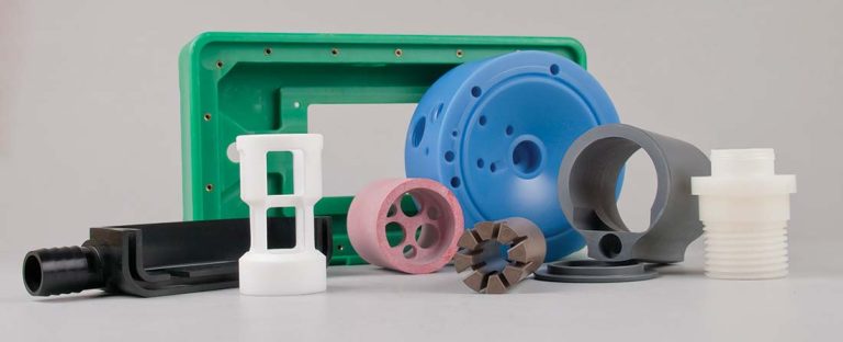
ほとんどすべて熱可塑性材料 射出成形を行うことができ、いくつかの熱硬化セットと液体シリコーンもプロセスと互換性があります。さらに、それらの特性は、フィラーと添加物(ガラス繊維や炭素繊維など)を追加するか、異なるペレット(PC/ABSブレンドなど)をブレンドして、望ましい外観と機能を実現することで調整できます。以下は、一般的に使用される射出成形材料の概要です。
材料 特性 ポリプロピレン(PP) 超低密度とコスト、優れた流れと耐薬品性。低い剛性と不十分なUV/酸化耐久性。 ポリエチレン(PE) 強度または柔軟性のために、HDPE/LDPEで利用可能な化学耐性。硬直性が低く、接着が不十分です。 ポリスチレン(PS) 非常に硬く寸法的に安定しています。形作りやすい;衝撃強度が低い脆性。 アクリロニトリルブタジエンスチレン(ABS) 丈夫で耐衝撃性、良好な表面仕上げと成形性。中程度の耐熱性、長期の気象性が低い。 酢酸(POM) 高い剛性、低摩擦と水の取り込み、優れた寸法の安定性。限られた高温性能。 アクリル(PMMA) 光学的に透明、UV/気象耐性、高い剛性。脆くてストレスの亀裂を起こしやすい。 ナイロン(PA) 優れたタフネス、摩耗と疲労抵抗、高強度。乾燥と設計の補償を必要とする吸湿性(水分の取り込み)。 ポリブチレンテレフタレート(PBT) 強い、硬い水分吸収と良好な電気断熱材。中程度の収縮 - 適切なゲーティングを必要とします。 ポリカーボネート(PC) 衝撃強度、自然透明度、広い温度範囲。ストレスの亀裂に敏感で、均一な壁の厚さが必要です。 ポリエーテルエーテルケトン(ピーク) 例外的な化学/熱抵抗と機械的強度。非常に高価で、特殊な成形が必要です。 熱可塑性エラストマー(TPE) 柔軟性と柔らかいタッチのようなラバー、優れた化学/天候抵抗。負荷ベアリング容量の低下。 熱可塑性ポリウレタン(TPU) 優れた耐摩耗性と弾力性、良好な負荷を負担します。カビに固執することができます - 最適化されたドラフトとリリースを必要とします。 PC/ABS PCよりも容易な成形性とABSよりも優れた安定性を備えたバランスの取れた靭性と耐熱性。中程度の耐薬品耐性。
一部の設計上の考慮事項
部品が最小限の欠陥で一貫して生産され、可能な限り低いコストで確実に生成されるようにするために、設計者はいくつかの確立されたガイドラインに従う必要があります。次のセクションでは、射出成形用の部品を設計する際の重要な考慮事項の概要を説明します。
壁の厚さ
壁の厚さは、機械的な性能、全体的なコスト、射出成形部品の外観に影響します。デザイナーが理解する必要がある2つの壁の厚さの用語があります。
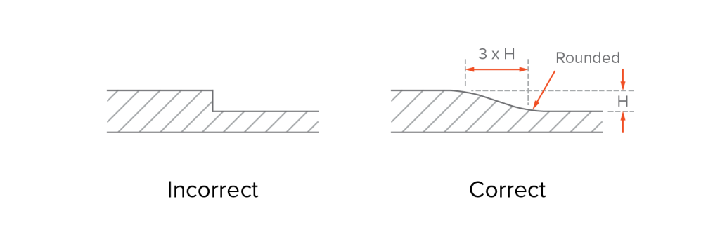
可能な限り、あなたの部品に均一な壁の厚さを維持してください。これにより、冷却さえ促進され、より一貫した収縮が生じ、ストレス濃度、変形、およびその他の射出成形欠陥の減少に役立ちます。
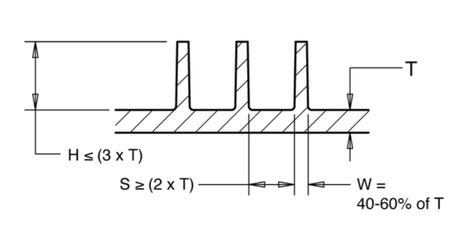
均一な壁の厚さは、必ずしもすべての壁がまったく同じ厚さでなければならないことを意味するわけではありません。むしろ、隣接する壁のセクション間の大きなバリエーションを最小限に抑えることを強調しています。一般に、壁の厚さは隣接する壁の40%から60%以上でなければなりません。機能的または構造的な理由に厚さの変動が必要な場合、遷移は、厚さの違いの少なくとも3倍の長さのチャンファーまたはフィレットを使用することで、流れや冷却の急激な変化を避けることを徐々に使用する必要があります。
公称壁の厚さとは、部品のターゲットまたは平均厚さを指し、設計の出発点として機能します。適切な壁の厚さは、十分な部分の強度と材料の廃棄物を減らすのに役立ちます。また、金型の設計、処理パラメーター、機器のセットアップ、材料の選択の基礎も定めています。
厚すぎる壁は、収縮と変形のリスクを高めます。また、より多くの材料とより長いサイクル時間を必要とし、生産コストを押し上げます。一方、薄すぎる壁は、速すぎるか、空気を閉じ込める可能性があり、短いショットにつながる可能性があります。
これらの問題を回避するために、選択した素材の推奨範囲内に壁の厚さを常に保ちます。以下は、一般的なプラスチック樹脂の推奨される壁の厚さのリストです。
材料 壁の厚さをお勧めします) 壁の厚さをお勧めしますmm) 酢酸(POM) 0.030–0.120 0.76–3.05 アクリル(PMMA) 0.025–0.500 0.64–12.70 アクリロニトリルブタジエネスレン(ABS) 0.045–0.140 1.14–3.56 ナイロン(PA) 0.030–0.115 0.76–2.92 ポリブチレンテレフタレート(PBT) 0.080-0.250 2.032-6.350 ポリカーボネート(PC) 0.040–0.150 1.02–3.81 ポリエーテルエーテルケトン(ピーク) 0.020-0.200 0.508-5.080 ポリエーテルイミド(PEI) 0.080-0.120 2.032-3.048 ポリエチレン(PE) 0.030–0.200 0.76–5.08 ポリフェニルスルフォン(PPSU) 0.030-0.250 0.762-6.350 ポリプロピレン(PP) 0.035–0.150 0.89–3.81 ポリスチレン(PS) 0.035–0.150 0.89–3.81 熱可塑性エラストマー(TPE) 0.025–0.125 0.64–3.18 熱可塑性ポリウレタン(TPU) 0.025–0.125 0.64–3.18
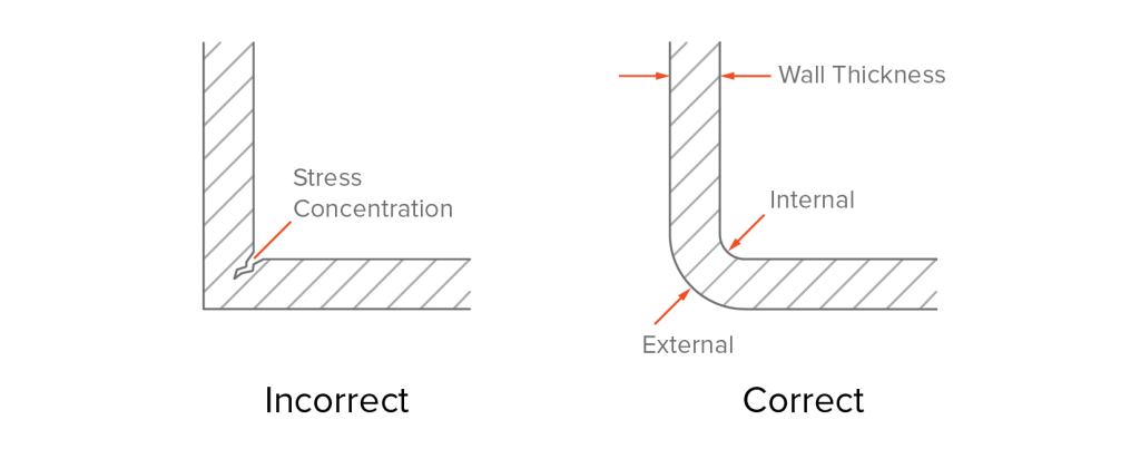
コーナー
鋭い角は、ストレスを集中させ、ターゲットをより困難にし、カビの表面の摩耗を加速する傾向があります。材料は、これらの鋭い遷移で不均一に蓄積または冷却する可能性があり、その結果、フローラインまたはその他の欠陥が生じます。さらに、鋭い角は、多くの場合、型を形成するためにEDM(電気放電加工)を使用する必要があり、ツールコストが上昇します。
ベストプラクティスは、丸い角を使用することです。一般的な設計ガイドラインは次のとおりです。
▪壁の厚さの少なくとも50%の内部半径を使用します(スペースが制限されている場合は最低25%)。
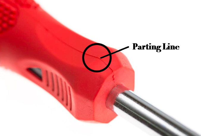
別れの行
別れの線は、金型の2つの半分が出会う場所で形成された縫い目です。通常、成形部品の表面に表示され、射出成形の避けられない特徴です。別れのラインの配置は、カビの複雑さ、生産効率、および部品の最終的な外観または機能に影響します。
直感的なアイデアは、部品の中央をまっすぐに分割線を置くことです。しかし、これは常に可能であるとは限りません - または実用的でさえあります。実際には、視覚的な魅力、機能、およびカビの複雑さのバランスをとるために、別れのラインを戦略的に配置する必要があります。例えば:
目に見えない領域に別れの線を非表示にします。良い例は、レゴのレンガです。ここでは、上面ではなく下側に微妙に隠されているため、最も目に見える表面が完璧なままであることが保証されます。
シーリングサーフェス、交配穴、ねじ付きインサートなどの重要な機能領域に分割線を配置しないでください。これらの領域に分かれたラインが存在すると、わずかな寸法の変動、フラッシュ、または不十分なフィット感を引き起こす可能性があります。
フィレットや湾曲した表面に別れのラインを配置しないでください。これらの機能には、より高いカビ精度が必要であり、製造コストが増加し、カビの閉鎖が不完全になり、フラッシュまたはその他の欠陥が発生する可能性があります。代わりに、金型の構造を簡素化し、ターゲット効率を向上させ、ツーリングとメンテナンスコストを削減するために、自然な分割線(例えば、鋭いエッジ、ステップ、またはブレークラインなど)に沿って配置ラインを配置する必要があります。
より複雑なジオメトリのために、設計者は不規則な別れのラインを導入するか、アンダーカットや隠された機能に対応するためにサイドアクションを組み込む必要がある場合があります。
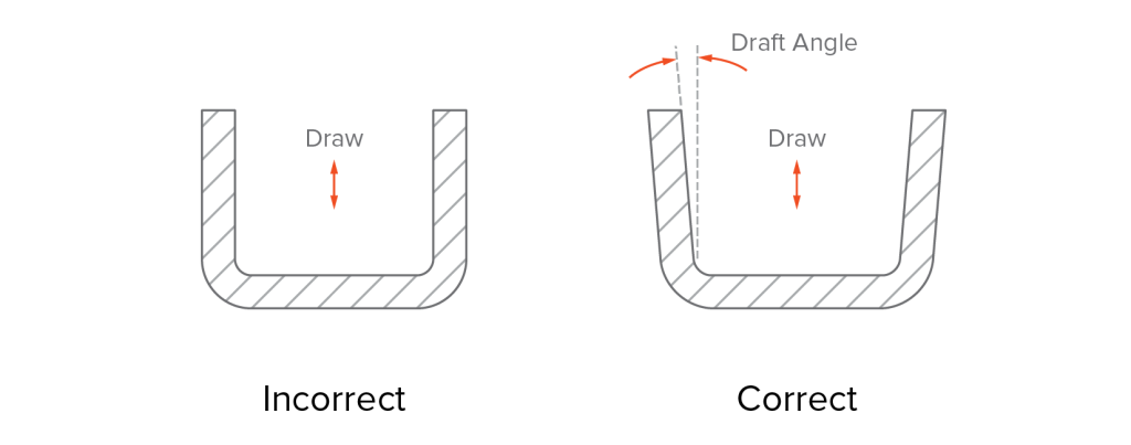
下書き
ドラフトは、ージ型から滑らかな排出を可能にするために、注入型部品の垂直表面に適用される角度です。適切なドラフトがなければ、部品は金型の表面にしっかりと接触し、排出中に過度の力を危険にさらします。これにより、品質が低下し、廃棄部品につながる可能性があり、ツールに損傷を与える可能性があります。
多くのCADソフトウェアプログラムにより、ドラフト角度を簡単に追加できますが、不必要な複雑さを防ぐために設計の最終段階にそれらを適用することをお勧めします。適切なドラフト角を決定するとき、次の要因を考慮する必要があります。
プラスチックが異なると、異なるフロー特性があり、必要なドラフト角に影響します。ポリプロピレン(PP)、ポリエチレン(PE)、ポリスチレン(PS)などの材料は、一般に優れた流れ特性と低粘度を持っています。これらの材料の場合、通常、1°から3°のドラフト角度で十分です。対照的に、エポキシやフェノール樹脂のような熱硬化プラスチックは、滑らかな排出を確保するために、より大きなドラフト角(3°以上)が必要です。
ドラフトは、射出成形部品の表面のテクスチャーと滑らかさに関連しています。よりスムーズな仕上げにはドラフトが少なくなりますが、より重いテクスチャはより多くのものが必要です。例えば:
▪滑らかな仕上げのために、約1〜2°のドラフト角度で一般的に十分です。
射出成形中、金型からのテクスチャーは部品の表面に伝達されます。あなたが設計している製品の種類は、金型仕上げの選択に影響を与えます。 Society of the Plastics Industry(SPI)やドイツのエンジニア協会(VDI)などの業界組織、およびMold-Tech(MT)やYick Sang(YS)などの企業は、磨かれたテクスチャの金型仕上げの標準化された分類を確立しています。これらの標準は、表面仕上げ要件に基づいて、適切なドラフト角度の選択を導くのに役立ちます。
以下の表面仕上げチャートには、最も一般的な仕上げの推奨ドラフト角度がリストされています。
SPI標準 ドラフト(°) カビテクテクスチャー 下書き (°) A-1 0.5 MT-11000 1.0 A-2 0.5 MT-1010 1.5 A-3 0.5 MT-11020 2.5 B-1 1.0 MT-1030 3.0 B-2 1.0 VDIテクスチャ-PC B-3 1.0 VDI-18 1.0 C-1 1.5 VDI-24 1.5 C-2 1.5 VDI-33 3.0 C-3 1.5 YSテクスチャ D-1 2.0 ys1xx 1.0 D-2 2.5 ys3xx 4.0–5.5 D-3 3.0 ys5xx 6.0–12.0
金型の開く方法でドラフト角度を設定します。金型の方向を「描画」します。それ以外の場合、部品はエジェクターピンを保持し、適切にリリースされない半分に固執することができます。さらに、すべての垂直壁だけでなく、穴やボスなどの機能にもドラフトを適用してください。
たとえば、4つの穴のある長方形の部分を想像してください。穴が空洞に向かってドラフトされている場合、部品は成形後にそこに立ち往生したままになる可能性があります。代わりに、それらをコア側にドラフトします - エジェクターシステムが住んでいる場所 - ピンは部品をきれいに押し出すことができます。
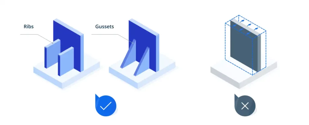
rib骨とガセット
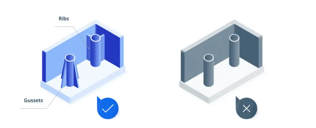
rib骨とガセットはどちらも、局所的な構造を強化し、全体的な壁の厚さを増やすことなく部分的な剛性を改善するために使用されます。
rib骨は細い、壁のような壁のような壁のような部分の表面から伸びており、しばしば広く薄い壁のある領域または内側の箱型の特徴を横切って、負荷を均等に分配し、全体的な剛性を改善します。効果的なリブの設計を確保するには、これらのベストプラクティスに従ってください。
▪rib骨の厚さは主な壁の厚さの40〜60%でなければなりません。
ガセットは、壁、ボス、またはrib骨の接合部に配置された小さな三角形または台形のプレートが、局所的な高応力ポイントを強化するためです。 Gusset Designのベストプラクティスには次のものがあります。
▪ガセットは通常、支持している壁の約3分の1から半分の厚さでなければなりません。▪ガセットは、強化しているボスやrib骨よりも背が高くはありません。実際、多くの場合、そのボスの高さの約30〜50%である必要があることが多く、ほとんどの場合サポートを提供するのに十分です。
ボス
ボスは、インサート、セルフタッピングネジ、またはアセンブリまたは取り付け用のピンを受け取るように設計された円筒形の機能です。また、全体的な構造強度に寄与する円形のrib骨と見なすこともできます。自立したボスは避ける必要があります。壁自体に完全に統合されるのではなく、rib骨やガセットを使用して、常に隣接する壁や表面に接続してください。
ボスを設計するときは、次のことを覚えておいてください。
▪スクリューの場所など、構造の完全性や固定強度が必要なボスを配置します。
アンダーカット
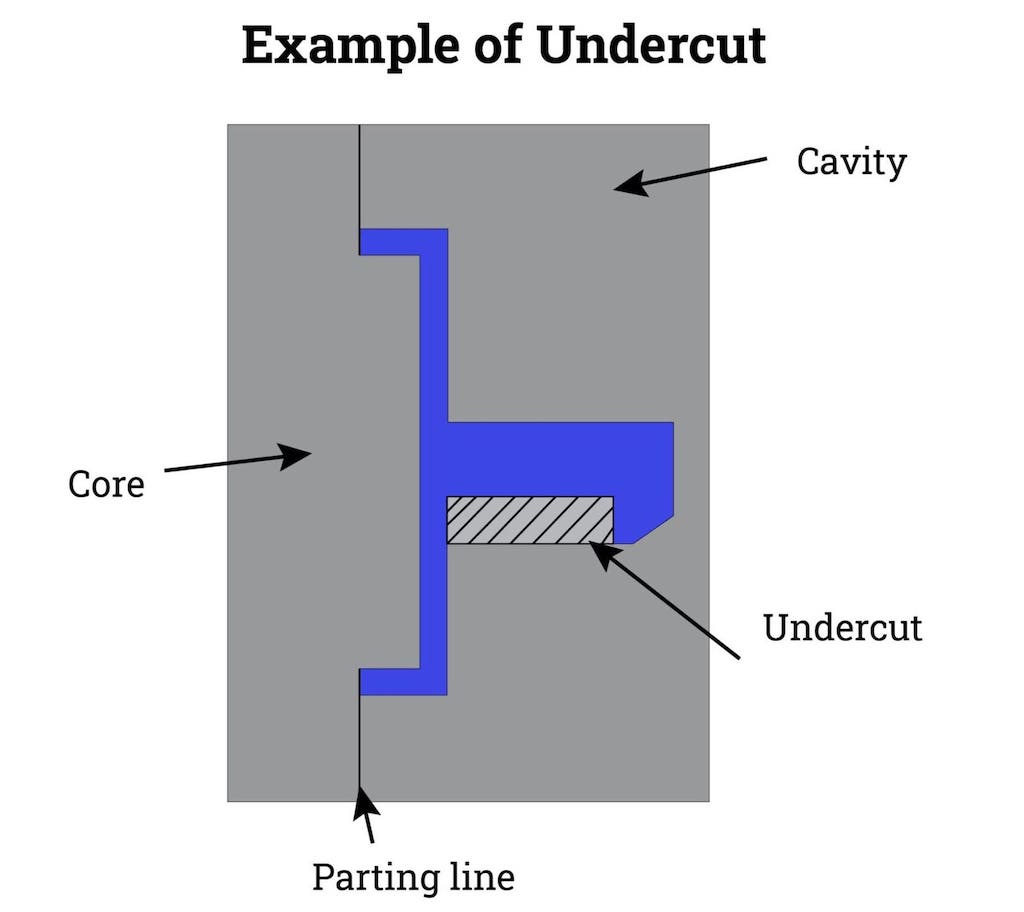
アンダーカットは、部品と片または両方のカビの半分の間にインターロックを作成する凹状または張り出した特徴であり、カビの開口方向に沿ってきれいな排出を防ぎます。一般的な例には、フック、スナップフィット、穴、溝、および金型の分離方向に垂直または横方向のサイドスロットが含まれます。
機械的機能やアセンブリの適合にはアンダーカットが必要な場合がありますが、通常、スライドコア、リフター、またはカムなど、カビの複雑さ、サイクル時間、製造コストを増加させる追加のツールが必要です。不適切に設計されたアンダーカットは、排出障害、一部の歪み、過度の摩耗、またはツールの故障を引き起こす可能性があります。
アンダーカットのいくつかの設計ガイドラインは次のとおりです。
▪可能な場合は、ジオメトリを変更したり、部品を再配向したり、別れのラインをシフトしたりして、型のプル方向と整合し、凹部を排除するように特徴を排出することにより、アンダーカットを回避します。エラストマー)。アンダーカットの高さが非常に薄い壁で≤0.3mmでない限り、PP/PEを避けてください。面取りで30°〜45°の鉛を導き、顔面から0.5°〜1°ドラフトを追加して、滑らかな排出を確保するために隆起します。
テキストとシンボル
テキストとシンボル(たとえば、部品番号、ロゴ、リサイクルマークなど)は、トレーサビリティ、ブランド、または規制のコンプライアンスのために、成形部品に一般的にエンボスまたはデボスされています。ここにいくつかの役立つヒントがあります:
▪刻まれたテキストにはより複雑な金型ツールが必要であり、ツールの摩耗が加速され、特に高ボリュームまたは複雑なデザインのためにコストが増加するため、可能な場合は埋め込み(刻まれた)ではなく、上昇(刻まれた)テキストを使用します。一貫したプラスチックの流れ、およびツールの摩耗を減らします。
公差
射出成形耐性は、公称設計からの部品の寸法の許容偏差を定義します。設計では、アセンブリインターフェイス、シーリンググルーブ、穴の位置などの重要な機能に、これらが直接影響を与えるため、より緊密な許容範囲を適用する必要があります。非負荷をかける表面の幅などの非批判的な寸法の場合、緩い許容範囲を使用して製造コストを削減できます。
2つの一般的な許容レベルがあります。
商業的許容範囲: 比較的緩んで(通常±0.1 mmまたは±0.004 ")、ほとんどの非重要な機能で低コストでうまく機能します。細かい許容範囲: よりタイト(通常、±0.05 mmまたは±0.002 ")、高精度部品に必要で、ツールと製造コストが高くなります。
設計中、材料の収縮に従って寸法公差を調整する必要があります。プラスチックが異なると、縮小率は異なります。セミ結晶材料(PA、PP、PE、POMなど)は、アモルファス材料(ABS、PC、PMMAなど)よりも縮小します。収縮は一般に予測可能ですが、樹脂製剤または処理条件(溶融温度など)のわずかな変動が最終的なパーツサイズに影響を与える可能性があります。部品サイズが大きくなると、収縮の変動がより顕著になります。材料に応じて、収縮関連の耐性は約±0.002in/in(0.05mm/mm)を期待する必要があります。
耐性スタックアップ分析もマルチパーツアセンブリで考慮する必要があります。これは、個々の特徴(穴など)が指定された許容範囲内であっても、累積変動が不整合につながる可能性があるため、特に異なる部品の複数の穴がファスナーが通過する必要がある場合です。
カビの耐性も最終的な部分の品質に影響することに注意してください。標準の金型機械加工許容値は約±0.005 "(0.13mm)ですが、高精度の部品にはより厳しい許容値が必要になる場合があります。さらに、金型は時間の経過とともに摩耗を経験し、寸法ドリフトにつながる可能性があります。
カビのデザインの基本
部品の設計と金型の設計は、射出成形製品の成功を決定する際に密接にリンクされています。一部の設計がジオメトリと機能に焦点を当てているため、MOLD DESIGNはこれらの要件を製造可能なツールに変換します。次のセクションでは、金型設計の基本的な側面の概要を説明します。
金型ベースとキャビティレイアウト
金型ツールは、標準の金型ベース、キャビティとコアインサート、および移動するコンポーネント(スライド、リフター、エジェクタープレートなど)で構成されています。金型ベースは、ホールディングガイドの柱、サポートプレート、排出システムなどの剛性フレームワークを提供しますが、キャビティとコアの挿入物は部品の形状を定義します。一緒に、彼らは各部分がどれほど正確かつ一貫して成形されているかを制御します。
良い金型のデザインは次のとおりです。
▪標準的なベース(DMEまたはHascoなど)を使用して、費用対効果の高い調達と摩耗したコンポーネントの簡単な交換を行います。
ゲート
ゲートは、溶融プラスチックがカビの空洞に流れるエントリポイントです。それらのサイズ、形状、配置は、部分的な外観、構造強度、およびフローマークや溶接ラインなどの成形欠陥の存在に大きな影響を与えます。
▪大きな部品が必要です。完全な充填のために圧力と流量を維持するには大きなゲートが必要です。
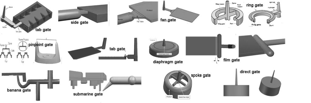
ゲートは、マニュアルまたは自動のトリミング方法によって分類でき、特定のタイプは特定のパーツジオメトリにより適しています。下の写真は、門の一般的な例を示しています。
▪エッジゲート(標準ゲート): 分割線に沿った長方形の断面。フラットまたは長方形の部品に最適です。より良い流れのためにテーパーにすることができます。ファンゲート: 大きなまたは薄い壁に囲まれた部品の広いフレアの開口部。せん断を最小限に抑え、充填バランスを改善します。タブゲート: せん断と熱を吸収するための小さなタブを備えたエッジゲートバリアント。せん断に敏感な材料に適しています。ダイアフラムゲート: 同心円のコアの周りの円形ゲート。優れたバランスですが、トリミングが困難でコストがかかります。リングゲート: ラジアルフィリングのためにコアの周りの連続リング。チューブ型部品で使用されます。スポークゲート: ラジアルリブを備えたリングゲートバリアント。対称的な管状部分に適していますが、同心性を維持することは困難です。フィルム(フラッシュ)ゲート: 大きな/薄い部品のための非常に薄く、広いゲート。均一な充填を保証しますが、手動トリミングが必要な長い痕跡が残ります。
▪潜水艦(トンネル)ゲート: 別れのラインの下の角度のあるエントリ。最小限の傷のために排出中に自動が破壊されます。ピンポイントゲート: 別れのライン内の小さな直接ゲート。高流量材料と化粧品の部品に最適です。マルチキャビティまたは精密型で一般的です。
ランナーシステム
ランナーシステムは、溶融プラスチックをスプルーから門まで、カビの空洞に導きます。ランナーのデザインは、特に多室またはファミリ型において、材料の流れ、サイクル時間、および部分の品質に影響を与えます。効率的なランナーシステムにより、溶融プラスチックがすべての空洞に均等に流れることが保証されます。バランスの取れた流れは、寸法変動、短いショット、溶接線などの欠陥を防ぎます。不均一な分布は、局所的な過熱または下着を引き起こす可能性があり、それが強度と表面仕上げの両方に影響します。
ランナーチャネルの形状とサイズは、フローの動作と処理効率に直接影響します。フルラウンドランナーは圧力損失を減らしますが、ツールの複雑さを増加させますが、台形または半円形のランナーは機械加工しやすくなりますが、効率が低くなります。特大のランナー廃棄物とゆっくりした冷却。小さめのものはフローを制限し、不完全な充填を引き起こす可能性があります。マルチキャビティ型では、ランナーは対称で均等に分布して、各キャビティが同時に充填されるようにする必要があります。
ランナーシステムには2つの主要なタイプがあります。
コールドランナー よりシンプルで費用対効果が高いですが、削除またはリサイクルする必要がある過剰な材料(ランナースクラップ)を生成します。ホットランナー この廃棄物を排除し、流れと温度をより適切に制御しますが、より高いツールコストとメンテナンスの取り組みが必要です。
ランナーシステムは、ゲートおよび冷却システムと連携して設計する必要があります。適切に最適化されたレイアウトは、サイクル時間を短縮し、一貫性を向上させ、効率的で高品質の成形をサポートします。
エジェクターピン
エジェクターピンは、固化したら、成形部品を空洞から押し出すために使用されます。それらの配置とデザインは、部分の品質、排出効率、カビの寿命に大きな影響を与えます。設計の推奨事項は次のとおりです。
▪分離線の近くなどの非仕切り表面にエジェクターピンを配置します。▪ピンの数と種類は、部分ジオメトリ、ドラフト角、壁の厚さなどの要因に依存します。たとえば、エッジまたはファンのゲートを備えた部品は、バランスの取れた排出のために追加のピンが必要になる場合があります。
冷却システム
冷却システムは、収縮、サイクル時間、および最終的な部品品質を制御するためにカビの温度を維持します。チャネルは均一な冷却のためにルーティングする必要があり、厚い部分の周りの間隔(空洞から3〜5mm)で締め付けます。冷却ラインは、ゲート、ランナー、または排出ハードウェアと競合しないようにしてください。適切なチャネル直径(通常6〜10mm)とバランスの取れたマニホールドは、熱の一貫性をさらに改善し、サイクル時間を短くします。
ExpertおよびプロトタイプDFMフィードバックのためにChiggoを使用します
射出成形の設計が製造可能性、パフォーマンス、コストにどのように影響するかをより明確に理解できるようになったので、今後は前進する時が来ました。設計の準備ができたら、Chiggoは引用のリクエストとともに無料のDFM(製造可能性の設計)分析を提供します。この分析は、カビ製造と射出成形に関連する潜在的な問題またはリスクを特定するのに役立ちます。
次は何ですか?作成プロトタイプ ツールが始まる前に、設計の決定を検証するのに役立ちます。チグゴはここにあります 射出成形の旅の各ステップを導き、デザインから生産へのスムーズな移行を確保します。