究極の引張強度(UTS)は、材料が壊れる前に耐えることができる最大応力の尺度です。 UTSは通常、引張テストを実行し、エンジニアリングストレス対ひずみ曲線を記録することによって見つかります。として集中的なプロパティ、UTSは、緊張下の材料の性能を比較するために不可欠です。エンジニアが、故障せずに引張荷重に抵抗する必要がある構造とコンポーネントの適切な材料を選択するのに役立ちます。
この記事では、最終的な引張強度、テストおよび計算方法、およびアプリケーションについて説明します。
究極の引張強度とは何ですか?
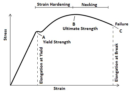
引張強度または究極の強度としても知られる究極の引張強度(UTS)は、壊れる前に材料が耐えることができる最大量の引張(引っ張りまたは伸縮)応力です。引張試験中、材料は最初に弾性変形を受けます。降伏点を超えると、最大応力に達するまで卑劣に変形し続けます。 UTSは、エンジニアリングストレス - 伸縮曲線に対するピーク応力を表し、材料の引き離された抵抗を反映しています。

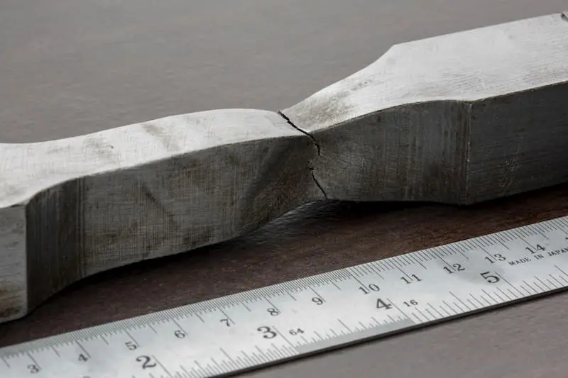
図に示すように、ポイントBは究極の引張強度です。この時点の後、延性材料では、標本はネッキングを受け、骨折まで維持できるストレスの減少につながりますが、脆性材料は、著しいネッキングなしでUTに到達した直後に骨折します。
UTSは、負荷を負担するアプリケーションの材料選択の重要なメトリックであり、エンジニアが最大予想負荷の下で壊滅的にコンポーネントに失敗しないようにするのに役立ちます。ただし、UTSのみでは、材料がどれだけ耐えることができるかを捉えていないため、現実的なサービス条件下での材料の行動を完全に理解するために、降伏強度、骨折の靭性、伸長などの他の機械的特性と一緒に評価する必要があります。
引張強度はどのようにテストされていますか?
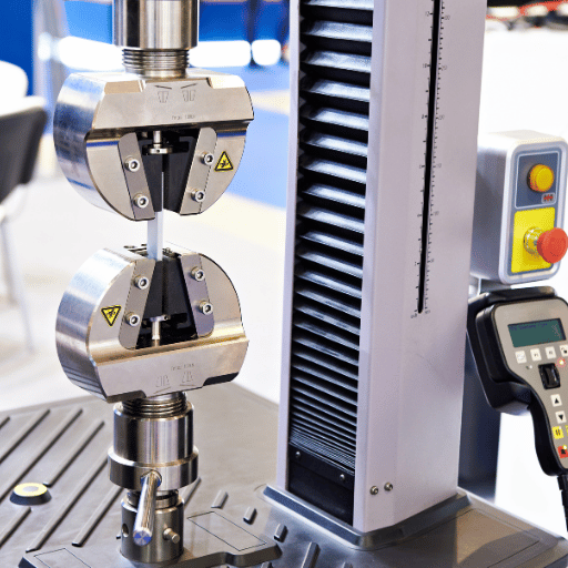
引張強度は応力として定義され、単位面積あたりの力として測定されます。一般にユニバーサルテストマシン(UTM)として知られている引張試験機を使用して、材料の引張強度を評価できます。両端に標本を保持する2つのグリップがあります。
テスト中、このマシンは、材料が骨折するまで着実に増加する引張荷重を適用します。プロセス全体を通して、適用された力と対応する試験片の伸長を継続的に記録します。テストデータは応力 - ひずみ曲線を生成し、そこから最大応力値(最終的な引張強度(UT))が特定されています。
この引張試験の結果は、引張強度を計算するために必要な重要なデータを提供します。この計算では、最大記録された力と標本の元の断面積を使用して、UTを正確に定量化します。
引張強度はどのように計算されますか?
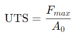
引張強度は、元の断面領域に壊れる前に材料が負担できる最大引張力を分割することによって計算されます。最終的な引張強度を計算するための式は次のとおりです。
強度(またはストレス)=力 /面積
数学的には、これは次のように表現できます。
ここで、FMAXは引張試験中に記録された最大荷重であり、A0は標本の初期断面積です。この計算により、ストレス単位、通常はパスカル(PA)、メガパスカル(MPA)または平方インチあたりのポンド(PSI)の究極の引張強度が得られます。ピーク荷重を標本の元の領域に関連付けることにより、エンジニアはサイズや形状に関係なく、異なる材料を一貫して比較できます。
材料の究極の引張強度に影響する要因は何ですか?
UTSは、引張応力に対する材料の抵抗の基本的な特性を説明していますが、固定または不変の価値ではありません。 UTは、さまざまな材料と処理因子のために大きく異なる場合があります。次の重要な側面は、材料のUTに影響を与える可能性があります。
化学組成
材料の合金要素または添加物は、その原子結合、相構造、および全体的な強度に直接影響します。たとえば、鉄に炭素を追加すると、パールトまたはマルテンサイト(Fe₃c沈殿物を使用)が生成されます。オーステナイトステンレス鋼のニッケルは、FCC相を安定させます。
粒サイズ(微細構造)
より細かい穀物は一般に、より高いUTにつながります。穀物構造を改良(縮小)する熱処理は、より多くの穀物境界を生成し、転位の動きをブロックし、金属の変形をより困難にします。これはホール - ペッチ効果として知られています。逆に、粗い穀物(ゆっくりと冷却または過熱による)は強度が低くなります。
熱処理
熱処理は、材料の微細構造を変化させるため、UTを大幅に変更できます。鋼の場合、クエンチングはオーステナイトを硬いマルテンサイトに冷却し、UTを急激に増加させますが、その後の焼き戻しは内部ストレスを緩和し、延性を回復し、よりバランスのとれた機械性能を生成します。対照的に、アニーリングはゆっくりとオーステナイトを粗い真珠岩とフェライトに変換し、鋼を柔らかくし、延性と機密性を高め、通常はUTを低下させます。
一方、アルミニウム合金は、溶液処理に続いて老化(沈殿硬化)に依存しています。この(沈殿硬化)。この微細な沈殿物が形成され、UTSを改善するために転位運動を妨害します。
欠陥と転位
材料内の欠陥はUTSに影響します。高密度の転位または小さな沈殿物粒子は、変形を妨げ、UTSを増加させる可能性があります(これが、ワーク硬化と一部の合金沈殿物がどのように機能するかです)。ただし、ボイド、亀裂、包含物などの大きな欠陥は、UTを減らすストレス濃縮器として機能します。一般に、清潔で欠陥のない結晶格子(制御された強化欠陥は別として)は、より高いUTをもたらす傾向があります。
温度
動作温度は強い影響を及ぼします。ほとんどの材料は、高温で弱くなり(原子はより自由に移動し、結合が弱くなります)、UTは熱とともに減少します。たとえば、高純度のニッケルは、室温での〜550 MPaから500°Cで〜350 MPaに低下します。逆に、金属を冷却する(サブゼロまたは極低温まで)、通常はUTSが増加します(よりも脆くなる可能性があります)。
異なる材料の究極の引張強度の例
以下は、いくつかの一般的なエンジニアリング材料の典型的なUTの範囲です。
| 材料(合金/状態) | UTS(MPA) |
| 軽度の炭素鋼(A36) | 400–550 |
| 高炭素鋼(1090) | 696–950 |
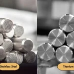
| ステンレス鋼(304/18-8) | 510–620 |
| アルミニウム(6061-T6) | 290–310 |
| アルミニウム(7075-T6) | 510–538 |
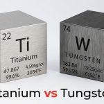
| チタン(TI-6AL-4V) | 900–950 |
| 銅(純粋、99.9%) | 200-250 |
| 真鍮(C260) | 345–485 |
究極の引張強度(UTS)のアプリケーション
UTSは、構造、機械、および安全性の高いアプリケーションに対する材料の適合性を評価する際の重要な指標です。 UTが重要な役割を果たす典型的なアプリケーション領域を次に示します。
構造工学
橋、建物、およびその他の民間インフラストラクチャでは、UTSは、エンジニアが鉄骨梁、鉄筋、およびその他の構造要素の負荷容量を決定するのに役立ちます。エンジニアはUTSデータを使用して、材料が十分な安全マージンで最大サービス負荷に耐えることができることを確認します。
航空宇宙
航空機の胴体、翼、ファスナーは、軽量のままである間、引張荷重に抵抗するために高いUTを持つ材料を必要とします。高強度アルミニウム合金、チタン合金、炭素繊維複合材料などの航空宇宙材料はすべて、UTS評価に基づいて選択されています。
自動車
シャーシフレームやサスペンションコンポーネントを含む自動車部品は、動的荷重の下でクラッシュワージ性と耐久性を確保するためにUTSに依存しています。これらのアプリケーションには、一般に高強度の鋼と軽量合金が選択されます。
圧力容器とパイプライン
適切なUTを備えた材料は、圧力容器やパイプラインに不可欠であり、ガスまたは液体を高い内圧で運ぶため、破裂や漏れを防ぐのに役立ちます。 ASMEボイラーや圧力容器コードなどの標準は、UTを主要な設計パラメーターとして使用します。
消費者製品とファスナー
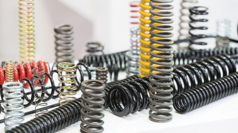
日常の製品でさえ、UTSは、エンジニアがネジ、ボルト、スプリング、プラスチックハウジングの材料を指定するのを支援し、繰り返し使用または偶発的な過負荷中に失敗しないようにします。
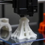
3D印刷部品のUTに影響を与える重要な要因
3Dプリントされた部品のUTは、機械的特性がレイヤーごとのビルドでは本質的に異方性であるため、従来の成形または偽造コンポーネントのUTよりもはるかに可変です。特に、層間層の接着はレーカー内強度よりも弱く、その接着は、押出温度、印刷速度、材料レオロジーまたは硬化挙動、および方向を構築する多くの要因に依存します。
押出温度
新しく堆積したフィラメントが層の下にどれだけうまく融合しているかを決定します。温度が低すぎると、フィラメントは十分に溶けず、流れが不十分で層間界面で小さなギャップが生じます。高すぎると、ポリマーが劣化したり、過度に流動的になったりする可能性があり、垂れ下がった、ひも、または歪んだ特徴を引き起こす可能性があります。
ベストプラクティス:ノズル温度をフィラメントの推奨処理範囲の上端に設定します。通常は、公称融点より上で約5°C上で、小さなステップトライアル(+5°C増分)を実行して、最適な結合温度を特定します。
印刷速度
前のレイヤーのホットマテリアルの滞留時間を制御します。高速速度は、完全に溶けない「冷たい」堆積につながる可能性があります。非常に遅い速度は、特徴を過熱して変形させる可能性があります。
ベストプラクティス:バランスの速度と流れ - 各ビーズが融合や弦を引き起こすことなく、融合するのに十分な長さのポリマーのガラス遷移(または治療のしきい値)を上回ることができる中程度の移動速度を使用します。
物質的なレオロジーまたは硬化行動
PLA、ABS、PETGなどの熱可塑性科学物質では、溶融粘度は、フィラメントが前の層を流れ、濡れていることを示しています。フォトポリマープロセスでは、樹脂化学(モノマー型、分子量)および光検証剤濃度の硬化の深さと架橋密度。曝露が不十分であるため、層の接着が弱くなります。
ベストプラクティス:最適な溶融流(例:硬いPETG上のPETG)または強い層の接着のために特異的に配合された樹脂を持つフィラメントを選択します。一貫したレオロジーを維持するために、吸湿性材料を乾燥させてください。
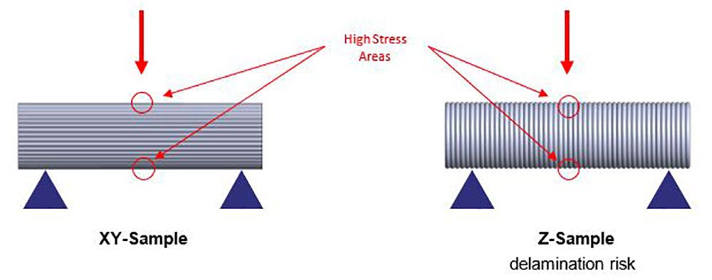
オリエンテーションを構築します
層間の接着は、レーヤー内結合よりも弱いため、UTSはX/Y平面で最も高くなりますが、Z軸に沿って大幅に低下します。
ベストプラクティス:プリントレイヤーに平行に一次荷重方向を整列し、可能な限りレイヤーインターフェイスに大きな引張荷重を適用しないようにします。
留意してください:
FEAを使用して印刷前に応力分布とUTを予測できますが、精度はプロセスに依存します。それは、ほぼ密度の高い等方性方法(金属PBFなど)に対して信頼性がありますが、異方性と微視的なボイドによるFDM/FFFプラスチックではそうではありません。
実際のパフォーマンスは、プリンター、環境、材料バッチによっても異なります。3Dプリンターは、従来の方法よりも再現性が低くなります。したがって、シミュレーションを超えて、堅牢なプロセス監視、材料検証、およびポストプロダクションテストを実装します。安全性または信頼性のある批判的な部分の場合、UTSを確認し、予期しない障害を防ぐために、物理的な引張試験が必須です。
結論
無数のエンジニアリングアプリケーションの中で、究極の引張強度(UTS)は、材料の評価と比較における重要なパラメーターです。その定義を理解することから、テストと計算の方法を習得することまで、UTSのしっかりした把握により、エンジニアはより安全で、より強力で、より効率的な製品を設計できます。
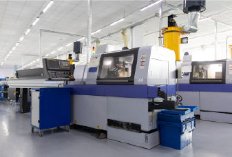
の専門知識を持ってCNC加工3D印刷では、UTS仕様を一貫して満たすコンポーネントを配信するため、必要な強度とパフォーマンスが得られます。今日お問い合わせください!
よくある質問
1.塑性変形と弾性変形の違いは何ですか?
弾性変形は可逆的です。材料は、荷重が削除された後、元の形状に戻ります。プラスチック変形は永続的です。ストレスが降伏強度を超えると、原子結合が再配置され、材料は降ろした後でも変形し続けます。
2。降伏強度とUTSの違いは何ですか?
降伏強度とは、材料が弾性の挙動からプラスチックの挙動に移行するストレスです。この時点で、永続的な(プラスチック)変形が始まります。究極の引張強度(UTS)は、壊れる前に材料が耐えることができる最大応力です。
3.引張応力は引張強度とどのように異なりますか?
唯一の違いは、引張強度が破壊前に材料が耐えることができる最大応力を指す一方、引張応力は、特定の負荷レベルでの断面積に対する印加力の比率を表します。
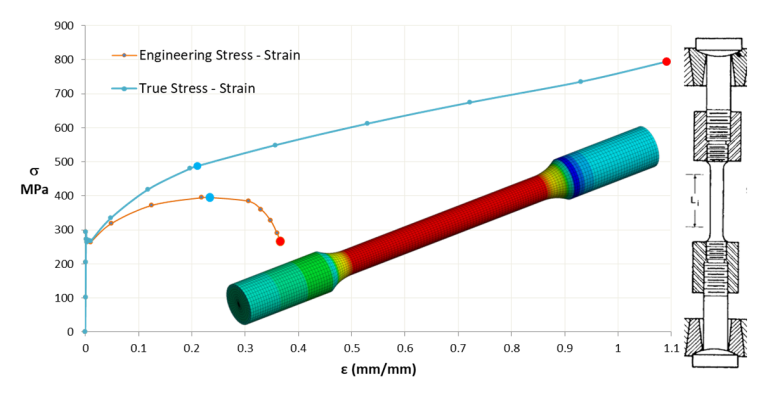
4.エンジニアリングストレスと真のストレスの違いは何ですか?
エンジニアリングストレスは、変形中の変化に関係なく、標本の元の断面積で割った力です。真の応力は、標本が変形するときに瞬間(実際の)断面積を使用して計算され、特に大きな株でより正確な応力の尺度を与えます。
5.骨折強度と引張強度の違いは何ですか?
引張強度(UTS)は、材料がストレスと伸縮曲線に到達する最大のエンジニアリング応力です。骨折強度(または破裂強度)は、標本が実際に壊れるエンジニアリング応力です。
延性材料では、UTSの後にネッキングして負荷をかける領域を減らします(σは元の領域を使用します)ため、骨折強度はUTSを下回ります。脆性材料では、無視できるネッキングがあるため、骨折強度は本質的にUTSに等しくなります。