Metall 3D -Druck geht schnell vor - mit schnelleren Build -Geschwindigkeiten, besserer Materialleistung und breiteren Anwendungsbereichen. Dieser Leitfaden zeigt Ihnen, wie Sie das Beste aus der Metall -Additive Manufacturing (AM) herausholen: Wir werden über die Haupttypen von Metall -3D -Drucktechnologien, die gemeinsamen Materialien und über die Kosten sprechen. Wir werden auch Metall AM mit subtraktiv (subtraktiv () vergleichen (CNC -Bearbeitung) und formative Methoden (Metallguss), damit Sie den richtigen Prozess für Ihren Teil, Ihr Budget und Ihre Zeitleiste auswählen können.
Was ist Metall 3D -Druck?
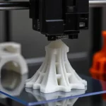
Ähnlich wie bei allen anderen 3D -Druckprozessen (z. B. Polymer -3D -Druck) bauen Metall 3D -Drucker Teile, indem sie Material jeweils eine Schicht basierend auf einem digitalen 3D -Design hinzufügen - daher der Begriff additive Herstellung. Nur dieses Mal verwendet das Verfahren Metallpulver, Draht oder Polymergebundenes anstelle von Kunststoffen.
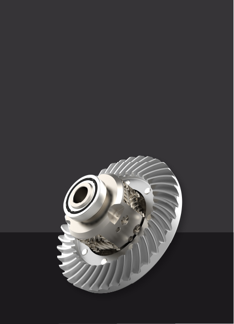
Auf diese Weise können Teile mit Geometrien gebaut werden, die mit traditionellen Methoden und ohne Bedarf an speziellen Werkzeugen wie Formen oder Schneidwerkzeugen nicht hergestellt werden können. Ebenso wichtig ist, dass die zunehmende geometrische Komplexität nur geringe Auswirkungen auf die Baukosten hat, sodass organische, topologie optimierte Strukturen praktisch sind. Die resultierenden Teile sind leichter (typischerweise eine Gewichtsreduzierung von 25% –50%) und häufig steifer, was für die Luft- und Raumfahrt und andere Hochleistungsfelder von entscheidender Bedeutung ist.
Diese Entwurfsfreiheit ermöglicht auch die Konsolidierung der Montage: Mehrere Komponenten, und alle ihre Befestigungselemente, Fugen und Leckwege können zu einem einzigen gedruckten Teil werden, der mehrere Funktionen gleichzeitig ausführt. Arbeitsabfälle, Lead -Zeiten schrumpfen und die Wartung ist einfacher, da weniger zu versammeln, auszurichten oder zu bedienen. Der Metall -3D -Druck ist jedoch im Vergleich zu vielen herkömmlichen Methoden immer noch teuer und konkurriert noch nicht mit den Einheitenkosten bei höheren Volumina.
Eine kurze Geschichte des Metall -3D -Drucks
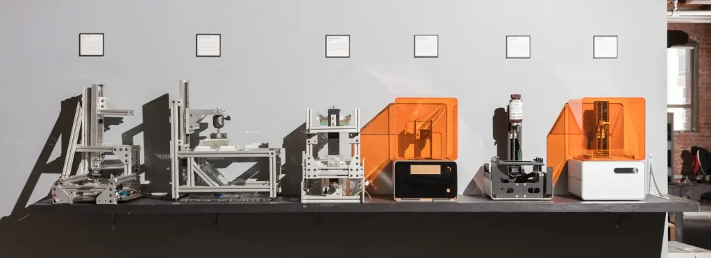
In den späten 1980er Jahren entwickelte Dr. Carl Deckard von der University of Texas den ersten 3D -3D -Drucker, der ursprünglich für Kunststoffe entwickelt wurde. Diese Technologie wurde zur Grundlage für das selektive Lasersintern (SLS), eine Methode, die sich später auf Metal 3D -Druck erstreckt.
1991 führte Dr. Ely Sachs vom MIT einen 3D -Druckprozess ein, der heute als Binder -Detting bezeichnet wird. Diese Methode des Metallbindemittels wurde 1995 für Exone lizenziert.
1995 reichte das Fraunhofer -Institut in Deutschland das erste Patent für das Laserschmelzen von Metallen ein, das den Grundstein für das selektive Laserschmelzen (SLM) legte, eine der am häufigsten verwendeten Methoden für den heutigen Metall -3D -Druck. In dieser Zeit spielten Unternehmen wie EOS und verschiedene Universitäten eine Schlüsselrolle bei der Weiterentwicklung der Technologie.
Der Metall -3D -Druck wuchs Anfang der 2000er Jahre aufgrund der hohen Ausrüstungskosten und Materialien langsam. Um 2012, als die Patente für Schlüsseltechnologien wie SLM, DMLS und EBM zu Ende ging, fielen die Lizenzgebühren und öffneten die Tür für neue Konkurrenten. Diese Verschiebung löste Innovation aus und zog große Investitionen von Unternehmen wie GE, HP und DMG Mori an, senkte die Kosten und beschleunigte die Akzeptanz in verschiedenen Branchen.
Heute,Nach dem VorrangforschungsberichtDer globale Metall -3D -Druckmarkt wurde im Jahr 2024 mit 9,66 Milliarden USD bewertet und wird voraussichtlich von 12,04 Milliarden USD im Jahr 2025 auf 87,33 Mrd. USD bis 2034 mit einer CAGR von 24,63%wachsen. Der Markt wird von der Nachfrage nach schnellem Prototyping, maßgeschneiderten und komplexen Komponenten und wachsenden Nutzungen in Luft- und Raumfahrt- und Automobilzusammenfassungen angetrieben.
Arten von Metall -3D -Drucktechnologien
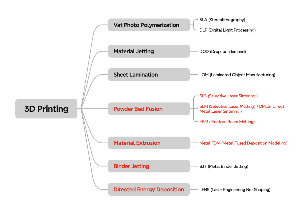
Es gibt viele Metall -3D -Drucktechnologien auf dem Markt, aber vier der am häufigsten verwendeten Pulverbettfusion (PBF), Bindemittel -Dets, Metallfusionsablagerungsmodellierung (Metall -FDM) und gerichtete Energieabscheidung (DED). Im Großen und Ganzen fallen sie in zwei Mechanismen: Schmelzen und Sintern.
PBF- und DED -Schmelzmetall -Ausgangstock (Pulver oder Draht) mit hohen Energiequellen , wie Laser, Elektronenstrahlen oder Bögen, um nahezu vollständige Teile zu erzeugen. Im Gegensatz dazu erzeugen Metal FDM und Binder Jitting zuerst einen „grünen“ Teil mit einem Polymerbindemittel, und diskutieren Sie ihn dann unter dem Schmelzpunkt. Die endgültige Dichte ist in der Regel niedriger als vollständig geschmolzene Prozesse, und fast immer ist eine zusätzliche Nachbearbeitung erforderlich.
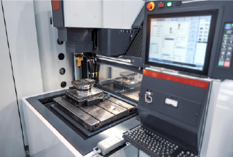
Pulverbettfusion (PBF)
Die Pulverbettfusion (PBF) wird allgemein als die am häufigsten verwendete Metall -3D -Druckfamilie angesehen. Darunter,Selektives Laserschmelzen (SLM)UndDirektes Metalllasersintern (DMLs), die seit über 20 Jahren verwendet werden, sind heute die technologisch reifsten Metall -3D -Druckprozesse, gefolgt von, gefolgt vonElektronenstrahlschmelzen (EBM), eine weitere Schlüsselmethode, die insbesondere für Titanlegierungen in Luft- und Raumfahrt- und medizinischen Anwendungen verwendet wird.
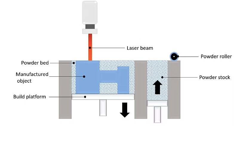
Der PBF -Prozess beginnt mit dem Vorheizen der Baukammer, die zuerst mit einem inerten Gas gefüllt ist, zu einer optimalen Temperatur. Eine dünne Metallpulverschicht wird dann über die Build -Plattform verteilt. Der Laser (in SLM und DMLS) oder Elektronenstrahl (in EBM) wird an das Pulverbett gerichtet, wodurch die Pulverpartikel selektiv schmelzen oder verschmolzen, gemäß dem Entwurf des Teils. Die Partikel verschmelzen zusammen, um die erste Schicht zu bilden, und die Plattform wird dann leicht abgesenkt. Eine neue Pulverschicht wird über die vorherige verteilt, und der Vorgang wird für Schicht wiederholt, bis der Teil vollständig gebaut ist.
Da die Bautemperaturen sehr hoch sind (oft> 1000 ° C für viele Legierungen), sind in der Regel Stütze erforderlich, um das Teil an Ort und Stelle zu halten und zu verhindern, dass sich das Warping an thermischem Stress verhindert. Nach dem Abkühlen wird das überschüssige nicht -melzierte Pulver entfernt (gebürstet, gesprengt oder abgesaugt), und die Stützen werden durch Schneiden entfernt oder entfernt oderDraht EDM.Der Teil wird dann Wärme behandelt, um Restspannungen zu lindern und die Materialeigenschaften zu verbessern. Abhängig von den Anforderungen muss der Teil möglicherweise zusätzliche Veredelungen wie CNC -Bearbeitung benötigt.Polierenoder andere Oberflächenbehandlungen, um die gewünschte Oberflächenqualität und dimensionale Genauigkeit zu erreichen.
Merkmale gemeinsamer Pulverbettfusionsmethoden
Hier ist eine detaillierte Vergleichstabelle für die drei Haupt -PBF -Metall -3D -Drucktechnologien:
Eigentum
Selektives Laserschmelzen (SLM)
Direktes Metalllasersintern (DMLs)
Elektronenstrahlschmelzen (EBM)
Energiequelle
Laser
Laser
Elektronenstrahl
Materialien verwendet
Sphärische Metallpulver mit einer einzelnen Schmelztemperatur; Besuchen Sie Aluminiumlegierungen, Titan, Edelstahl, Werkzeugstahl und bestimmte Legierungen
Sphärische Metallpulver mit variablen Schmelzpunkten; Besuchen Sie Edelstahl, Titanlegierungen, Nickellegierungen, Edelmetalle und Werkzeugstähle
Sphärische Metallpulver wie Titanlegierungen, Kobalt-Chrom-Legierungen, Nickel-Superalloys und andere Hochleistungsmaterialien
Verfahren
Laser schmilzt das Pulver vollständig, um dichte Teile zu erzeugen
Lasersintern (schmilzt Pulver, aber es verflüssigt es nicht vollständig)
Elektronenstrahl schmilzt Pulver in einer Vakuumumgebung
Volumen aufbauen
Typischerweise klein bis mittel (variiert je nach Maschine)
Typischerweise klein bis mittel (variiert je nach Maschine)
Typischerweise größere Build Volumina im Vergleich zu SLM/DMLs erhältlich
Geschwindigkeit aufbauen
Moderat (abhängig von Laserleistung und Teilkomplexität)
Moderat (variiert mit Material und Teilgröße)
Langsamer (aufgrund der Verwendung von Elektronenstrahl- und Vakuumumgebung)
Gedruckte Teileigenschaften
Innere Porosität, weniger als 0,2 - 0,5%; hohe Dichte und ausgezeichnete mechanische Stärke
Die Teileigenschaften ähneln SLM, aber es kann aufgrund des Sinterprozesses eine geringfügige Porosität mehr auffällig sein
Die Porosität ist im Allgemeinen niedrig, kann aber aufgrund der langsameren Aufbaugeschwindigkeit und der größeren Schichtdicke etwas höher sein als SLM
Dimensionsgenauigkeit
± 0,1 mm
± 0,1 mm
± 0,1 mm
Typische Buildgröße
250 x 150 x 150 mm (bis zu 500 x 280 x 360 mm)
250 x 150 x 150 mm (bis zu 500 x 280 x 360 mm)
500 x 500 x 380 mm oder größer
Gemeinsame Schichtdicke
20-50 μm
20-50 μm
50-150 μm
Unterstützung
Immer erforderlich
Immer erforderlich
Immer erforderlich
Typische Oberflächenrauheit
Ra 8 - 10 μm
Ra 8 - 10 μm
RA 20-60 μm
Kosten pro Teil
$$$$$
$$$$$
$$$$$$
Schlüsselanwendungen
Teile mit hoher geometrischer Komplexität (organische, topologie optimierte Strukturen), die hervorragende Materialeigenschaften für die Steigerung der Effizienz der anspruchsvollsten Anwendungen erfordern
Ähnlich wie SLM
Hochleistungsanwendungen, die starke, belastbare Teile erfordern, insbesondere in Luft- und Raumfahrt- und medizinischen Implantaten, in denen Titanlegierungen und andere hochfeste Materialien benötigt werden
Bindemittel Jitting
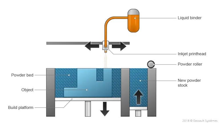
Bindemittel-Jetting wurde ursprünglich verwendet, um Vollfarbprototypen und Modelle aus Sandstein zu erstellen. Im Laufe der Zeit hat es für die Herstellung von Metallteilen beliebt, insbesondere aufgrund der Batch -Produktionskapazitäten. Während des Metallbindemittels -Dattes wird eine dünne Metallpulverschicht über die Build -Plattform verteilt. Ein mit Tintenstrahldüsen ausgestattetem Wagen verläuft dann über das Pulverbett und lässt Tröpfchen eines Bindmittels (typischerweise eine Mischung aus Polymer und Wachs), um die Metallpartikel miteinander zu verbinden. Sobald eine Schicht abgeschlossen ist, bewegt sich die Build -Plattform nach unten und eine neue Pulverschicht wird angewendet. Dieser Vorgang wiederholt sich, bis der gesamte Teil erstellt wurde.
Der Druckschritt beim Metallbindemittel -Jetching tritt bei Raumtemperatur auf und beseitigt Probleme wie thermische Effekte wie Verzerrungen und interne Spannungen, die bei Prozessen wie DMLs und SLM auftreten können. Unterstützungsstrukturen sind nicht erforderlich. Der gedruckte Teil bleibt jedoch in einem "grünen" Zustand, was bedeutet, dass er immer noch zerbrechlich ist und eine weitere Verarbeitung erfordert.
Es gibt zwei gängige Nachbearbeitungsschritte, mit denen der "grüne" Teil in eine vollständig feste Metallkomponente umgewandelt wird:
Infiltration:Nach dem Entfernen des Bindemittels gilt das Teil als „braun“ und weist eine signifikante innere Porosität auf (etwa 70%). Der „braune“ Teil wird dann in einem Industrieofen mit einem niedrigen Schmelzpunkt -Metall (oft Bronze) erhitzt, das die inneren Hohlräume füllt, was zu einem bi -metallischen Teil führt. Obwohl diese Methode die Stärke verbessern kann, wird sie heute weniger häufig verwendet, da ihre materiellen Eigenschaften denen von vollständig gesinterten Teilen unterlegen und ihre mechanische und thermische Leistung nicht so gut dokumentiert sind.
Sintern:Jetzt wird der bevorzugte Postprozess, der „grüne“ Teil, in einen Ofen platziert, in dem der Bindemittel abgebrannt wird und die Metallpulverpartikel zu einer vollständig dichten Komponente verschmelzen. Der Teil schrumpft normalerweise während des Sinterns um etwa 20%, sodass Teile etwas größer sind, um dies auszugleichen.
Eigenschaften des Metallbindemittels
Eigentum
Metall -Bindemittel -Jagd
Materialien verwendet
Derzeit beschränkt sich auf Edelstahl (z. B. 316L, 17 4PH), Werkzeugstähle (z. B. H13), Bronze/Kupferlegierungen und Inconel 625
Geschwindigkeit aufbauen
Schnellste unter allen Metall -3D -Drucktechnologien; Betten sind typischerweise dicht mit vielen kleinen Teilen pro Zyklus gepackt
Gedruckte Teileigenschaften
~ 1–2% Restporosität nach dem Sintern; Zugfestigkeit vergleichbar mit Gussmetall, aber die Lebensdauer der Müdigkeit ist aufgrund innerer Hohlräume signifikant niedriger
Dimensionsgenauigkeit
± 0,2 mm (± 0,1 nach Versuchen)
Typische Buildgröße
250 × 175 × 200 mm (bis zu 400 × 300 × 200 mm)
Gemeinsame Schichtdicke
Frühe Systeme dauerten 35–50 uM, hohe Durchsatzsysteme bis zu 100 µm).
Unterstützung
Nicht erforderlich
Typische Oberflächenrauheit
Ra10–15 µm als Sinterteile
Kosten pro Teil
$$$ (schneller Builds und kein Stützabfall)
Schlüsselanwendungen
Niedrige bis mittelgroße Läufe funktioneller Prototypen und komplexe Komponenten, bei denen Durchsatz und Einheitskosten mehr als maximale mechanische Leistung sind
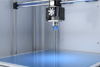
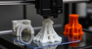
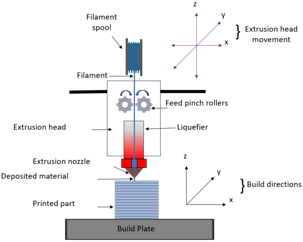
Die Metalltrusion ist eine Variation des klassischen FDM -Verfahrens für Plastik, aber anstelle von Thermoplastik werden Metallfilamente oder Stäbe verwendet, die typischerweise aus Metallpartikeln bestehen, die durch Polymer und/oder Wachs miteinander verbunden sind, so dass sie manchmal als Filamentmaterial -Extrusion bezeichnet wird.
Diese Stange oder Filament wird durch eine erhitzte Düse extrudiert und schichtweise abgelagert, um einen Teil basierend auf dem CAD-Modell zu erstellen. Gleichzeitig werden bei Bedarf Unterstützungsstrukturen gebaut. Die Schnittstelle zwischen der Unterstützung und dem Teil wird mit einem Keramik -Stützmaterial gedruckt, das später leicht manuell zu entfernen ist. Der resultierende „grüne“ Teil muss postbearbeitet werden, um Metall mit ähnlichen (aber nicht identischen) Bindemittel-Düsen zu werden. Der „grüne“ Teil wird zuerst eingeweicht oder thermisch behandelt, um den größten Teil des Polymer-/Wachs -Bindemittels (Entbindung) zu entfernen, und dann in einen Ofen gesintert, damit die Metallpartikel zu einem dichten, vollständig metallischen Stück verschmelzen. Während des Sinterns schrumpft der Teil ungefähr 15–20% in jede Richtung, sodass das CAD -Modell im Voraus vergrößert ist und möglicherweise eine Versuchsabstimmung erforderlich ist.
Eigenschaften der metallverhüllten Abscheidungsmodellierung
Eigentum
Modellierung der Metallverschmelzungsablagerung
Materialien verwendet
Derzeit sehr begrenzt auf 316L, 17 4PH, H13, Kupfer-/Bronzelegierungen und Inconel 625
Geschwindigkeit aufbauen
Mäßig; Langsamer als Bindemittel -Jetten, aber Setup/Iteration ist billiger und einfacher als SLM
Gedruckte Teileigenschaften
~ 90–97% Dichte (bis zu ~ 98% mit Hüfte); Zugfestigkeit in etwa Mim/Guss wie, typischerweise 20–40% niedriger als Schmiede; Ermüdungsfestigkeit durch Restporosität verringert
Dimensionsgenauigkeit
± 0,30 mm typisch; ± 0,15–0,20 mm erreichbar nach Stimmen und Schrumpfkompensation
Typische Buildgröße
250 × 220 × 200 mm
Gemeinsame Schichtdicke
100–200 um
Unterstützung
Erforderlich
Typische Oberflächenrauheit
RA 10–20 µm auf als gesinterte Oberflächen
Kosten pro Teil
$$ (niedrige Maschinen-/Materialkosten)
Schlüsselanwendungen
Funktionelle Metallprototypen, benutzerdefinierte Werkzeuge und ein Aus -/ -niedriges Volumenteile, bei denen Kosten und Einfachheit mehr als Spitzenleistung wichtig sind als Spitzenleistung
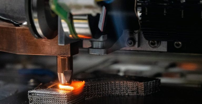
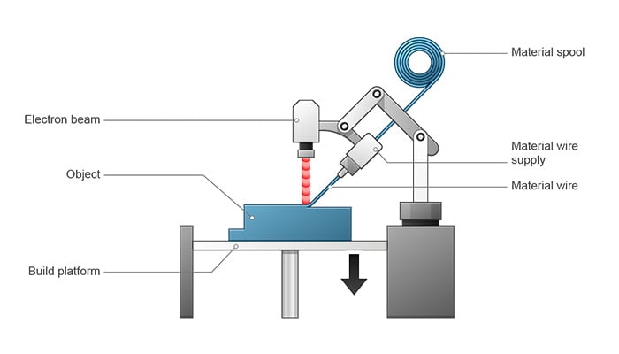
Regiesenergieablagerung (DED)
Die gerichtete Energieabscheidung (DED) verwendet eine fokussierte Wärmequelle, typischerweise einen Laser-, Elektronenstrahl- oder Elektro-/Plasma -Lichtbogen, um ein Schmelzpool auf dem Werkstück zu erzeugen, während Metallpulver oder Draht in die Baumaterial Perle von Perle gefüttert wird. Da sich der Druckkopf frei bewegen kann (häufig bei Multi -Achse -Strichträgen oder Robotern) und nicht durch ein Pulverbett beschränkt ist, ist Ded für die Reparatur oder das Hinzufügen von Merkmalen zu vorhandenen Teilen geeignet, und erzeugen große Nettoformkomponenten. Die Kompromisse sind mit groben Perlengeometrie, Rauten -Machung, die in der Regel eine grobe Perle -Perlen -Perlen -Scherz-, Rauten -Taste -Machung erfordern, und die Bearbeitung von Teilen und Fertigstellen.
Merkmale der gerichteten Energieabscheidung (DED)
Eigentum
Gerichtete Energieabscheidung
Energiequelle
Fokussierter Laser, Elektronenstrahl oder Elektro-/Plasma -Bogen
Materialien verwendet
Ähnlicher Legierungsbereich wie SLM; Standardschweißkabel und viele schweißbare Pulver sind nutzbar
Geschwindigkeit aufbauen
Vergleichbar mit (oder unten) Bindemittel -Ditting
Gedruckte Teileigenschaften
~ 95–99% Dichte (Drahtversorgungen oft höher als Pulver); Schweißnahe Mikrostruktur mit Richtungseigenschaften; Die Zugfestigkeit kann sich nach einer ordnungsgemäßen Wärmebehandlung befassen
Dimensionsgenauigkeit
± 0,5–1,0 mm typisch
Typische Buildgröße
Im Allgemeinen der größte der vier
Gemeinsame Schichtdicke
0,3–1,5 mm (Draht) oder 0,2–0,8 mm (Pulver), abhängig von Düse und Leistung
Unterstützung
Im Allgemeinen nicht erforderlich; Überhänge über Pfadplanung oder vorübergehende Vorrichtungen behandelt
Typische Oberflächenrauheit
Ra> 20–40 uM
Kosten pro Teil
$$ - $$$ (Ausrüstung ist teuer, aber eine hohe Ablagerungsrate senkt die Kosten für große Teile/Reparaturen)
Schlüsselanwendungen
Reparatur/Renovierung, Merkmal zusätzlich, große strukturelle Komponenten, in der Nähe von Nettoformblanks für die nachfolgende Bearbeitung
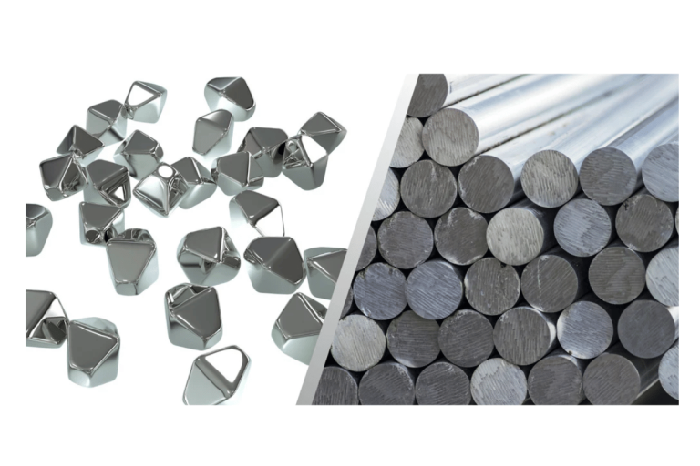
Materialien für Metall 3D -Druck
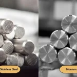
Während weit verbreitete technische Metalle wie rostfreie Stähle, Titan- und Aluminiumlegierungen für den Metall -3D -Druck erhältlich sind, sind viele andere Hochleistungs- oder benutzerdefinierte Legierungen, die in der herkömmlichen Herstellung verwendet werden, immer noch schwieriger zu beziehen oder sich für AM zu qualifizieren. Da druckbare Pulver in der Regel als kugelförmiger, eng und niedriger Sauerstoff erstellt werden, sind sie kostspielig zu machen, in weniger Legierungen erhältlich und immer noch mit relativ geringem Ertrag hergestellt. Die Anzahl der für den Metall 3D -Druck verfügbaren Metalle wächst rasant. Ingenieure können heute aus Legierungen wie Nickelbasis und Kobalt -Chromsystemen auswählen - Materials, die traditionell bekanntermaßen schwer zu maschinell zu bearbeiten sind.
Im Folgenden finden Sie einige Beispiele für gemeinsame AM -Metalle mit Edelstählen, Titan und Aluminium, die sich immer noch zu den am häufigsten verwendeten umsetzen:
Edelstähle
Werkzeugstähle
Titanlegierungen
Aluminiumlegierungen
Superalloys auf Nickelbasis
Kobalt -Chromlegierungen
Kupferbasierte Legierungen
Edelmetalle (Gold, Silber, Platin usw.)
Exotische Metalle (Palladium, Tantalum usw.)
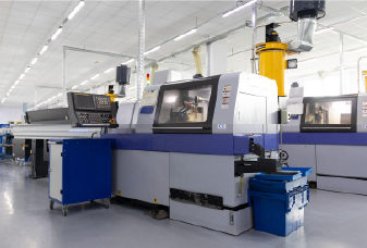
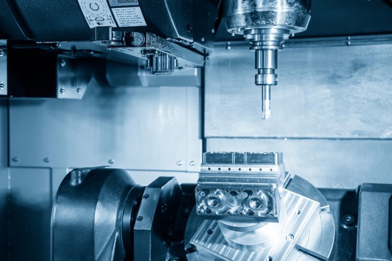
Metall 3D -Druck gegen traditionelle Herstellung
Wenn Sie nur ein paar komplexe Hochleistungsmetallteile benötigen, sind die Werkzeugebasis -Methoden langsam und kostspielig. Metall 3D -Druck vermeidet Werkzeug und macht eine komplexe Geometrie unkompliziert. Für einfache Designs oder große Mengen ist die CNC -Bearbeitung oder -abguss normalerweise billiger und schneller. Im Folgenden finden Sie einen Überblick darüber, wie Metall -3D -Druck mit subtraktiven (CNC -Bearbeitung) und formativen (Guss-) Prozessen über wichtige Aspekte vergleicht wird.
Aspekt
Metall 3D -Druck
CNC -Bearbeitung
Metallguss
Designfreiheit
Hervorragend für komplexe/interne Kanäle, Gitter, Teilkonsolidierung
Begrenzt nach Tool -Zugriff und Cuttergeometrie
Gut für organische externe Formen, braucht jedoch Entwurf/Kerne und kämpft mit vollständig geschlossenen Kanälen
Werkzeug / Setup
Keine Formen oder Schneidwerkzeuge; NUR STECKING/VERSÄTZUNGEN
Keine Formen, aber das Programmieren und Cam -Programmieren benötigten
Benötigt Formen/Stanze/Kerne; Hohe Vorabzeit und Kosten
Vorlaufzeit (Prototyp)
Stunden -Tage
Tage (Programmierung + Bearbeitung)
Wochen - Monate (Werkzeugbau)
Einheitenkosten vs. Volumen
Flach/hoch pro Teil; skaliert schlecht mit hohem Volumen
Abgenommen mit Volumen, aber jeder Teil benötigt noch Maschinenzeit.
Sehr niedrig bei hohem Volumen; Ausgezeichnete Skaleneffekte nach Werkzeug
Dimensionsgenauigkeit
Mäßig; Schrumpfung/thermische Effekte, prozessabhängiger (± 0,1–0,3 mm typisch für PBF).
Hoch; ± 0,01–0,05 mm üblich bei Präzisionsmerkmalen
Mäßig; ± 0,1–0,5 mm typisch (Investition
Oberflächenbeschaffung (maßgeblich)
Rauer (ra ~ 5–20+µm); Fertigstellen oft erforderlich
Gut - exzellent
Fair -Rough; muss normalerweise bearbeitet/polieren
Mechanische Eigenschaften
Kann sich nach ordnungsgemäßem HT/Hüfte der Schmelze nähern, aber Müdigkeit aufgrund von Porosität und Oberfläche oft niedriger; Stressabbau/Hüfte empfohlen
Verwendet Weught Stock → Vorhersehbare, hohe mechanische Leistung
Mikrostruktur gießen; Zug- und Müdigkeitseigenschaften im Allgemeinen untergebracht, können jedoch durch Wärmebehandlung (und manchmal eine Hüfte) verbessert werden
Teilgröße
Begrenzt durch Baukammer (außer DED)
Durch Maschinenumschlag begrenzt; Es gibt große Mühlen
Sehr große Teile machbar (Sandguss, Investitionsguss)
Materialbereich
Wachsende, aber immer noch weniger qualifizierte Legierungen
Fast jedes maschinelle Metall
Sehr breit; Die meisten legierbaren Legierungen, obwohl einige schwierig sind
Abfall- / Materialwirkungsgrad
Niedrig; Unbenutztes Pulver oft recycelt
Hoch -Chip -Abfall (sofern nicht separat recycelt)
Mäßiger Abfall (Gating/Riser -Schrott)
Nachbearbeitung
Entfernung der Unterstützung, Wärmebehandlung, Hüfte, Bearbeitung zur Toleranz
Abguss, mögliche Wärmebehandlung, Abschluss
Fett-, Wärmebehandlung, Bearbeitung bis endgültiger Toleranz
Beste Anwendungsfälle
Komplexes, niedriges Volumen, hohe Wertteile; schnelle Iteration; Interne Kanäle/Gitter
Präzisionsteile mit engen Toleranzen, mittelschwerer Volumina
Hohes Volumen oder sehr große Teile, in denen die Werkzeugkosten amortisiert werden können
Wählen Sie Metalldruck über die traditionelle Herstellung
1.Geometrie treibt die Leistung an
Interne Kanäle, Gitterfein, konforme Kühlwege und konsolidierte, einteilige Anordnungen sind schwer oder unmöglich zu maschine oder gießen.
2. Niedrige Mengen
Wenn Sie nur 1–50 Teile wie Prototypen, Pilotläufe oder Ersatzteile benötigen, zahlen sich selten aus Werkzeugbasismethoden aus. Die additive Herstellung vermeidet Formen und Sterben, wodurch die Einheiten bei sehr niedrigen Volumina relativ flach und angemessen bleiben.
3.. Schnelle Design -Iteration
Aktualisieren Sie einfach die CAD -Datei, Slice und Drucken - keine neuen Geräte oder Formen. CNC kann neu programmiert werden, benötigt jedoch häufig noch Änderungen des Werkzeugs, während fast immer neue oder modifizierte Werkzeuge gefordert werden.
4.Die Vorlaufzeit ist wichtiger als Einheitenkosten
Ein komplexes Metallteil kann oft in wenigen Tagen gedruckt werden - far schneller als die 6 bis 8 Wochen, die zum Aufbau und Beweis von Gusswerkzeugen erforderlich sind. Für AOG -Situationen (Flugzeuge am Boden) oder dringende Werkzeuge übertrumpft Speed pro Stückpreis.
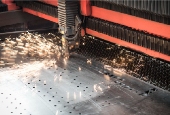
5. schwer zu maschinenlegierte Legierungen
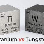
Inconel, CO CR und andere Superlegierungen sind teuer zu schneiden: Sie sind hart, härten schnell und zerstören Werkzeuge. Metall 3D -Druck überspringt das meiste Schneiden und vermeiden Sie Probleme mit dem Werkzeugverschleiß und Wärme. Hochenergieprozesse wie SLM oder EBM können sogar Komponenten aus ultrahoch hohen Schmelzmetallen wie Wolfram (3422 ° C) bauen, die nahezu unmöglich zu maschinellem Maschinenbetrag sind.
Die traditionelle Bearbeitung kann 80–90% eines Luft- und Raumfahrt -Billetes verschrotten. Mit Puderbett AM kann das meiste ungenutzte Pulver gesiebt und wiederverwendet werden, sodass Sie sich der nahe Nettoform viel näher näher sind. Beispielsweise benötigt eine Titanhalterung möglicherweise nur ~ 1,2 × seine endgültige Masse anstelle von ~ 6 ×.
7. auf Bedarf oder vor Ort Produktion
Drucken Ersatzteile, bei denen Sie sie verwenden, um Inventar und Logistik zu senken. Ein Offshore -Rig kann vor Ort einen benutzerdefinierten Edelstahlgriff drucken, anstatt Wochen auf einen bearbeiteten Austausch zu warten.
8. Reparieren oder Hinzufügen von Funktionen zu vorhandenen Teilen oder hinzufügen
Die Regie -Energieablagerung erbaut abgenutzte Turbinenklingen -Tipps oder fügt Bosse zu einem kostspieligen Gehäuse hinzu. Nach der Ablagerung stellt die CNC -Finishing genaue Profile wieder her, die häufig billiger als den gesamten Teil wiederhergestellt werden.
9. Topologieoptimierung und Leichtgewicht
Mit AM können Sie organische, optimierte Geometrien erkennen, die die Nichtlagermasse entfernen. Ein Luft- und Raumfahrtscharnier mit Gitterfeind kann das Gewicht um etwa 40% verringern und gleichzeitig die Stärke aufrechterhalten, ein Ergebnis, das für Mühlen oder Besetzung unpraktisch ist.
10. Montagekonsolidierung
Drucken Sie einen integrierten Teil anstatt viele Stücke zusammenzuarbeiten und zusammenzuspringen. Beispielsweise kann ein 12 -teiliger hydraulischer Verteiler mit mehreren Leckpfaden zu einem einzelnen gedruckten Block mit internen Kanälen werden. Dies bedeutet weniger Befestigungselemente, weniger Verbindungen, weniger Montagezeit und höhere Zuverlässigkeit.
11. Sonder- oder abgestufte Materialien
Benötigen Sie eine Nischenlegierung oder unterschiedliche Eigenschaften in verschiedenen Zonen? Einige AM -Systeme (insbesondere DED) können während des Builds Pulver oder Kabel wechseln, um Kompositionsgradienten zu erstellen. Forschungsteams drucken Ti -NB -Implantate mit weicheren Regionen für Knochenintegration und steifere Abschnitte für die Belastung, alle in einem Build.
Die Kosten für Metall 3D -Druck
Der Metall -3D -Druck ist im Allgemeinen teurer als Kunststoff, da die Kosten in drei Bereichen höher sind: Ausrüstung, Materialien und Nachbearbeitungsvorgänge. In den folgenden Abschnitten werden jeweils detailliert erörtert.
Ausrüstungskosten
Metalldrucker sind weitaus komplexer: Hochleistungslaser oder Elektronenstrahlen, inerte Gas- oder Vakuumkammern, Multi -Laser -Scan -Systeme, Präzisionsoptik und kontrollierte Pulverabgabe - alles weit zahlreiche als FDM- oder Photopolymermaschinen. Typische Preisbereiche nach Technologie:
SLM / DMLS (Laserpulverbettfusion): 300.000 bis 2.000.000 USD+
Regiesenergieablagerung (DED): 200.000 bis 1.000.000 USD+
Metall -Bindemittel -Jitting (Drucker plus Debind/Sinter -Einheiten): 300.000 - $ 800.000+
Metall FDM / Filamentmaterial Extrusion (Drucker plus Debind / Sinter -Einheiten): 100.000 bis 200.000 US -Dollar
Materialkosten
Metall 3D -Druckmaterialien kosten auch mehr als typische Kunststoffe. Atomisiertes Pulver ist bei Metall-Ausgangsmaterialien am teuersten, da es mit hoher Sphärizität, einem schmalen Bereich der Partikelgröße und einem sehr niedrigen Sauerstoffgehalt erzeugt werden muss. Draht für DED ist normalerweise billiger als Pulver, während das Polymer -Metallfilament (in Metall -FDM verwendet) immer noch billiger ist.
Atomisiertes Pulver (SLM, Bindemittel -Jetting): ungefähr 100 bis 600 US -Dollar pro kg, abhängig von der Legierung (Edelstahl am unteren Ende, Ti/Ni am oberen Ende)
Draht (DED): ungefähr 20 bis 80 USD pro kg; Pulver gefüttertes DED ist näher an Pulverbettpreisen
Polymergebundenes Metallfilament (Metall-FDM): ungefähr 50 bis 150 USD pro kg
Nachbearbeitung
Unterstützungsentfernung, Stressabbauzyklen, Hüft-, CNC -Veredelung und Oberflächenbehandlungen können Hunderte oder sogar Tausende von Dollar pro Bau oder pro Teil hinzufügen. Bindemittel -Jagd und Metall -FDM erfordern auch Debinding und Sintern, die Zeit und Kosten für Ofen hinzufügen.
Die folgende Tabelle ist eine Aufschlüsselung der typischen DMLS/SLM -Kosten -Mitwirkenden. Beachten Sie, wie die Nachbearbeitung einen erheblichen Anteil der Gesamtsumme ausmacht.
Produktionsschritt
Betrieb
Typische Kosten*
Herstellung
Metallpulver
200 bis 500 US -Dollar pro kg (materiell abhängig)
Maschinenzeit (eine Buildplatte)
2.000 bis 4.000 US -Dollar
Nachbearbeitung
Stressabbauzyklus
500 bis 600 US -Dollar pro Bau
Teil/Unterstützungsentfernung
100 bis 200 US -Dollar pro Teil
Wärmebehandlung / Hüfte
500 bis 2.500 US -Dollar pro Bau
CNC -Bearbeitung
500 bis 2.000 US -Dollar pro Teil
Oberflächen -Finishing / -beschichtung
200 bis 500 US -Dollar pro Teil
* Die tatsächlichen Zahlen variieren je nach Geometrie, Chargengröße, Material, Region und der Art und Weise, wie der Shop Overhead zuteilt. Eine einzelne Bauplatte kann je nach Teilgröße 1–12 Teile (oder mehr) enthalten.
Darüber hinaus werden Inerartgas-, Ofen- und Laserleistung, Pulversiedlung und Test, Staubexplosions-/Oxidationssicherheitsmaßnahmen sowie die laufende Wartung und Kalibrierung die Betriebskosten des Metall -3D -Drucks erheblich höher als die des Plastikdrucks.
Abschluss
Das Potenzial des Metall -3D -Drucks geht weit über die heutigen Luft- und Raumfahrt- und medizinischen Verwendungen hinaus. Da mehr Legierungen, intelligentere Maschinen und einfachere Postverarbeitung online kommen, werden Unternehmen in vielen Sektoren die reale Leistung validieren und die Kosten für maßgeschneiderte, komplexe Metallteile senken. Wenn Sie darüber nachdenken, Ihre Fähigkeiten mit Metal AM zu erweitern,sich in Verbindung setzen. Our team can help you decide when and how it makes sense.