عندما يتحدث المهندسون عن "الإجهاد" ، فإنهم يعنيون شيئًا مختلفًا تمامًا عن قلق الامتحان أو ضغط العمل. هنا ، الإجهاد هو القوة الداخلية لكل وحدة مساحة داخل المادة. قم بتمديد شريط مطاط أو سحب على حبل في شد الحبل ، وتشاهد إجهاد الشد في العمل-النوع الذي يجعل المواد استطالة تحت الحمل.
في هذه المقالة ، نوضح ماهية الإجهاد الشد ، وكيف يختلف عن الإجهاد الانضغاطي وعن قوة الشد ، والصيغ الرئيسية ، وكيف عوامل chiggo هذه الاعتبارات في التصنيع في العالم الحقيقي.
ما هو إجهاد الشد؟
يصف الإجهاد الشد كيف تتفاعل المادة عند محاولة تفكيكها. يتسبب في استطالة المادة على طول محور الحمل المطبق. بشكل رسمي ، يتم تعريفها على أنها القوة المطبقة F مقسومًا على المنطقة المستعرضة في هذه القوة.
الإجهاد الشد مقابل الإجهاد الضغط
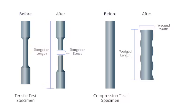
الإجهاد الشد هو عكس الإجهاد الضغط. يحدث إجهاد الشد عندما تعمل القوى على تمديد أو إطالة كائن ، بينما يحدث الإجهاد الانضغاطي عندما تضغط القوات أو تقصره. تخيل شريطًا معدنيًا صلبًا: اسحب على كلا الطرفين ويختبر إجهاد الشد ، مستمراً قليلاً. ادفع كلا الطرفين ، كما لو كانت تحاول سحقها بطولها ، ويعاني الشريط من الضغط على الضغط أو التقصير أو الانتفاخ.
يمكن أن تحدث هذه الضغوط أيضًا في نفس الوقت في أجزاء مختلفة من الهيكل. على سبيل المثال ، عندما يتحرك الأشخاص أو الآلات عبر لوح أرضي خرساني ، يتم دفع السطح العلوي للبلاطة في الضغط ، بينما يتم تمديد السطح السفلي في التوتر. إذا كان الإجهاد الشد في القاع يرتفع للغاية ، فقد تظهر الشقوق - وهذا هو السبب في أن المهندسين يضعون تعزيز الفولاذ هناك لمقاومة التوتر.
إجهاد الشد مقابل قوة الشد
إجهاد الشدهل الحمل الذي تواجهه مادة في لحظة معينة ، يتم التعبير عنها كقوة لكل وحدة مساحة. يرتفع ويسقط اعتمادًا على القوة المطبقة.قوة الشدعلى النقيض من ذلك ، هي خاصية مواد ثابتة - إنها الحد الأقصى لضغوط الشد التي يمكن أن تتعامل معها المادة قبل أن تعطي أو تكسر.
في الممارسة العملية ، يقارن المهندسون باستمرار الاثنين. إذا كان الإجهاد الشد الفعلي في جزء ما يظل أقل من قوة الشد ، فسيتمتد الجزء قليلاً ولكن يظل سليما. إذا تجاوز الإجهاد القوة ، يحدث الفشل. لهذا السبب تشمل التصميمات دائمًا هامش أمان ، مما يضمن أن يبقى ضغوط العالم الحقيقي أقل بكثير من القوة المعروفة للمادة المختارة.
صيغة الإجهاد الشد
يقيس الإجهاد الشد القوة الداخلية داخل مادة عندما يتم تمديدها. يتم حسابه بصيغة بسيطة:
σ = f / a
أين:
σ = إجهاد الشد (في pascals ، mpa ، أو psi)
F = القوة المطبقة (في نيوتن أو جنيه)
A = منطقة مستعرضة (في ملوم مربع أو في IN²)
تخبرنا هذه المعادلة مدى تركيز قوة السحب. حمولة أعلى أو منطقة مستعرضة أصغر تنتج إجهاد أعلى. على سبيل المثال ، يولد نفس الوزن المعلق على سلك رفيع أكثر بكثير من الإجهاد أكثر من الكابل الكثيف. هذا هو السبب في أن الكابلات أو القضبان أو الحزم في حجم المهندسين للحفاظ على الضغوط أقل بكثير من الحدود الآمنة للمواد المستخدمة.
لكن في حين أن هذه الصيغة تمنحنا القيمة العددية للإجهاد ، فإنها لا تكشف عن كيفية استجابة المادة نفسها. هل ستقلب فجأة ، أو ينحني بشكل دائم ، أو العودة إلى شكله الأصلي؟ للإجابة على ذلك ، يعتمد المهندسون على منحنى الإجهاد.
فهم منحنى الإجهاد
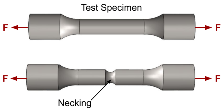
لإنشاء منحنى الإجهاد والضغط ، يتم وضع عينة اختبار (غالبًا ما تكون على شكل عظم الكلاب) في آلة اختبار الشد. يمسك الجهاز بكل نهاية ويسحبها تدريجياً ، وتمتد العينة حتى تنكسر. خلال هذه العملية ، يتم قياس كل من الإجهاد المطبق والسلالة الناتجة (التغير في الطول بالنسبة للطول الأصلي) بشكل مستمر.
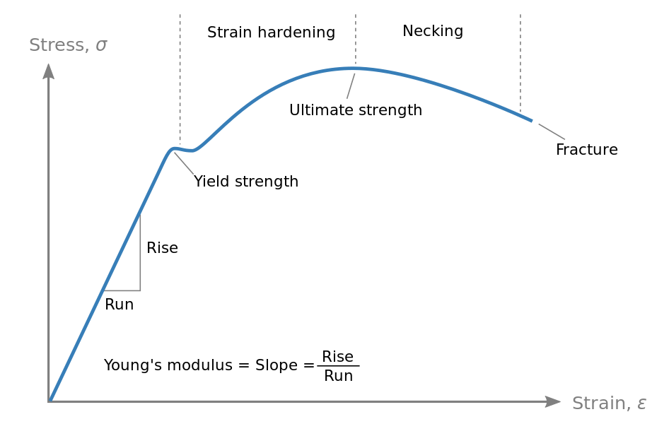
يتم رسم النتائج مع الضغط على المحور السيني والإجهاد على المحور ص. في هذا المنحنى ، يمكن تحديد عدة نقاط رئيسية:
منطقة مرنة
في البداية ، التوتر والسلالة متناسبة. هذه هي المنطقة المرنة ، حيث ينطبق قانون هووك (σ = e⋅ε). منحدر هذا القسم الخطي هومعامل مرن(معامل يونغ) ، مقياس الصلابة. في هذه المنطقة ، تعود المادة إلى شكلها الأصلي بمجرد إزالة الحمل.
نقطة العائد
مع زيادة التحميل ، يغادر المنحنى من الخط المستقيم. هذه هي نقطة العائد ، حيث ينتهي السلوك المرن ويبدأ تشوه البلاستيك (دائم). بعد هذه النقطة ، لن يتم استرداد المادة بشكل كامل شكلها الأصلي حتى إذا تمت إزالة الحمل.
قوة الشد النهائية (UTS)
يستمر المنحنى صعودًا في المنطقة البلاستيكية ، حيث وصلت إلى ذروة. هذه النقطة الأعلى هي قوة الشد النهائية (UTS) ، والتي تمثل الحد الأقصى من الإجهاد الذي يمكن أن يتحمله المادة قبل بدء التخلص (ترقق المترجمة).
نقطة الكسر
بعد UTS ، ينحدر المنحنى لأسفل كما أن رقاب العينة ولم يعد قادرًا على حمل الكثير من الحمل. في النهاية ، تنهار المادة عند نقطة الكسر. بالنسبة لمواد الدكتايل ، عادة ما يكون الإجهاد عند الكسر أقل من UTS بسبب الابتكار. بالنسبة للمواد الهشة ، يمكن أن يحدث الكسر فجأة بالقرب من الحد المرن ، مع تشوه بلاستيكي ضئيل أو معدوم.
تطبيقات العالم الحقيقي لضغط الشد
في أي موقف يتم فيها سحب الإجهاد الشد أو تعليقه أو تعليقه أو امتداده ما إذا كان بإمكانها حمل الحمل بأمان أو إذا فشلت. فيما يلي بعض التطبيقات والأمثلة الرئيسية:
الجسور والبناء
فكر في جسر معلق مثل جسر Golden Gate - تلك الكابلات الفولاذية الضخمة التي يتم لفها بين الأبراج تحت ضغط شد ثابت ، مما يدعم وزن الطريق والمركبات. يختار المهندسون الفولاذ ذو القوة العالية لهذه الكابلات حتى يتمكنوا من التعامل مع الأحمال الثقيلة بالإضافة إلى قوى إضافية مثل الرياح أو الزلازل دون فشل. البناء الحديث أيضا الاستخدام الذكي للتوتر. في الخرسانة الملموسة مسبقًا ، على سبيل المثال ، يتم تضمين الأوتار الفولاذية وتمديدها بحيث يمكن للحزمة التعامل بأمان بأمان.
الكابلات والحبال والسلاسل
تعتمد العديد من الأنظمة اليومية أيضًا مباشرة على إجهاد الشد. خذ مصعد ، على سبيل المثال: كابلاته الفولاذية في توتر مستمر ، لا تحمل فقط وزن السيارة ولكن أيضًا القوى الإضافية عندما تتسارع أو تتوقف. تعمل الرافعات على نفس المبدأ ، باستخدام الكابلات عالية الشد لرفع وتحريك الأحمال الثقيلة بأمان. حتى في شيء بسيط مثل الغيتار ، فإن الإجهاد الشد في اللعب - أكثر إحكامًا أن تقلب ربط التوليف ، وكلما زاد التوتر في السلسلة ، والذي يرفع الملعب حتى إذا تم دفعه بعيدًا ، فسوف تنكسر السلسلة في النهاية.
الآلات والمسامير
في الهندسة الميكانيكية ، يكون الإجهاد الشد أمرًا بالغ الأهمية. تعمل البراغي والمسامير في طائرة أو محرك سيارة من خلال التمدد قليلاً - الإجهاد الشد الناتج يخلق قوة التثبيت التي تجمع الأجزاء معًا. إذا تم تعزيز الترباس (الكثير من عزم الدوران عند التشديد ، أو الحمل المفرط في الاستخدام) ، يمكن أن ينتج عنه ويفشل ، مما قد يتسبب في تفكيك الجهاز. لهذا السبب يتم تصنيف البراغي من خلال الدرجات التي تشير إلى نقاط قوة عائدها وقوة الشد ، ولماذا يتم تشديد البراغي الحرجة على التوترات المحددة.
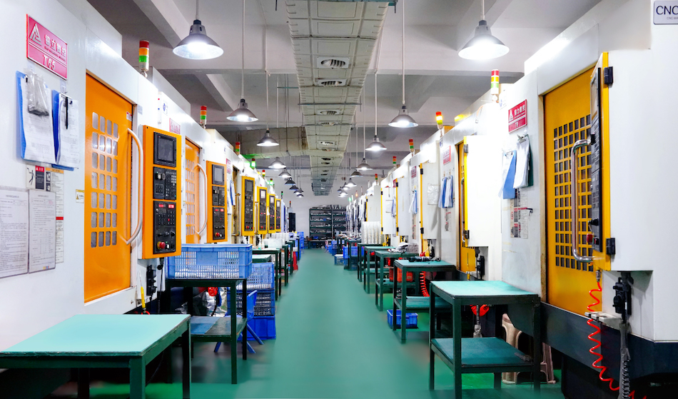
دمج إجهاد الشد في خدمات تصنيع تشيغو
إن معرفة نظرية الإجهاد الشد هو شيء واحد ، ولكن تصميم الأجزاء التي تؤدي تحت الأحمال الواقعية هي شيء آخر. في Chiggo ، نقوم بسد تلك الفجوة.
يدعمك فريقنا عبر الآلات CNC ، وصدع الحقن ، والمعادن ، والطباعة ثلاثية الأبعاد ، مع اعتبارات القوة المدمجة في كل مرحلة. سواء كنت تقوم بتطوير نموذج أولي أو تحجيم إلى الإنتاج ، فإننا نساعدك على اختيار المادة والعملية المناسبة حتى تلبي قطع الغيار متطلبات الأداء وتجنب الفشل المكلف.
اختيار المواد
الحماية الأولى ضد الفشل هي اختيار المادة الصحيحة. في Chiggo ، تأتي كل سبيكة و polymer المدرجة مع خصائص ميكانيكية تم التحقق منها ، بما في ذلك شد الشد والقوة العائد ، مدعومة ببيانات الموردين ، وعند الحاجة ، لاختبار الشهادات.
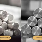
هذا يعني أنه يمكن للمهندسين مقارنة الخيارات ليس فقط على التكلفة أو النهاية ، ولكن على القوة المثبتة تحت الحمل. على سبيل المثال ، عند اتخاذ قرار بين الألومنيوم 6061-T6 و 7075-T6 ، تصبح قوة الشد مرشحًا مهمًا ، خاصة بالنسبة للأقواس أو العلب أو مكونات الحمل الأخرى.
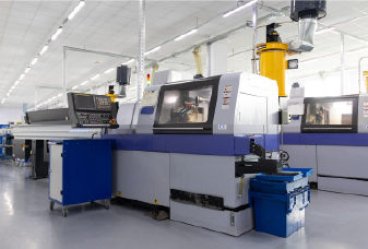
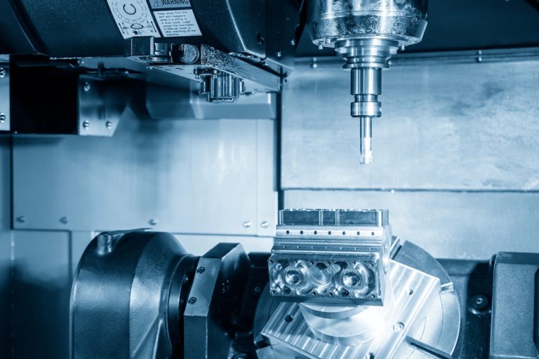
تصنيع CNC
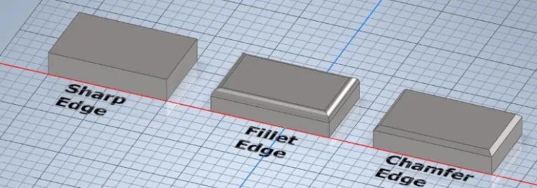
فيتصنيع CNC، تحتفظ المادة بقوته الخواص ، لذلك يمكن التنبؤ بالأداء عادة. المخاطر الحقيقية تأتي من تفاصيل التصميم. يمكن أن تعمل الزوايا الحادة أو الجدران الرقيقة أو التغيرات الهندسية المفاجئة كمركبات للإجهاد.
يحدد مهندسونا هذه المشكلات في وقت مبكر ويوصيون بالحلول العملية - مضافة شرائح ، أو ضبط سمك الجدار ، أو التحول إلى سبيكة أكثر صرامة. تساعد هذه التحسينات في ضمان إبقاء الجزء النهائي قدرته الشد الكاملة.
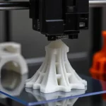
طباعة ثلاثية الأبعاد
الأجزاء المطبوعة ثلاثية الأبعاد تتصرف بشكل مختلف لأن قوتها تعتمد على اتجاه الطباعة. في FDM ، على سبيل المثال ، يكون الترابط على طول المحور z أضعف. هذا يعني أن الجزء قد يفشل بسهولة أكبر إذا تم تطبيق الحمل رأسياً.
تلعب اختيار المواد وإعدادات العملية أيضًا دورًا كبيرًا. تعتبر المواد البلاستيكية القياسية مثل PLA و ABS جيدة للنماذج الأولية ، في حين توفر النايلون من الدرجة الهندسية أو البوليمرات المقاومة للألياف الكربونية مقاومة أعلى بكثير للأجزاء الوظيفية. تؤثر الإبطال وسمك الطبقة واتجاه البناء على كيفية أداء الجزء تحت الحمل.
بالنسبة للمعادن ، يخلق التدفئة والتبريد السريع أثناء التصنيع المضافة ضغوطًا متبقية يمكن أن تشوه أو كسر الجزء. يعلم مهندسونا التوجهات الضعيفة والميزات الحساسة للإجهاد في وقت مبكر. قد نوصي بإعادة توجيه الجزء ، أو زيادة التثبيت ، أو اختيار مواد أقوى. عند الحاجة ، تساعد علاجات ما بعد البناء مثل الصلب في تخفيف التوتر وتحسين الاستقرار.
صب الحقن
في صب الحقن ، تعتمد قوة الشد ليس فقط على البوليمر نفسه ولكن أيضًا على كيفية تدفقه ويبرد في القالب. أثناء التعبئة ، غالبًا ما تتماشى السلاسل الجزيئية على طول مسار التدفق ، مما يجعل الجزء أقوى في اتجاه واحد ولكنه أضعف في آخر. يمكن للتبريد غير المتكافئ فخ الضغوط الداخلية ، مما يؤدي إلى تزييف أو علامات بالوعة أو تشققات تحت الحمل.
تفاصيل التصميم مهمة هنا أيضًا. يمكن أن تتحول الجدران الرقيقة أو وضع بوابة ضعف أو خطوط اللحام إلى نقاط إجهاد. من خلال مراجعة مسارات التدفق وسمك الجدار وتوازن التبريد في وقت مبكر من التصميم ، يساعد فريقنا في تقليل هذه المخاطر والحفاظ على الأجزاء المقولبة قوية ومستقرة.
صب
في الصب ، غالبًا ما تنشأ قضايا الشد أثناء التبريد والتصلب. نظرًا لأن الأقسام باردة بمعدلات مختلفة ، يمكن أن تتراكم الضغوط الداخلية ، مما يسبب الدموع الساخنة أو تشققات الانكماش أو التشويه.
يلعب تصميم العفن دورًا رئيسيًا. يمكن أن تركز التحولات السميكة إلى الرقيقة ، أو الزوايا الحادة ، أو الناهضين في وضع سيئ في التركيز على الإجهاد وتضعف الأداء. يساعد اختيار السبائك مع سلوك التصلب المستقر والسيطرة على معدلات التبريد في تقليل هذه المخاطر.
في Chiggo، مراجعة مهندسينا تصاميم قبل أن تبدأ الأدوات في اكتشاف الميزات عالية الخطورة في وقت مبكر. قد نوصي بتحولات أكثر سلاسة ، أو سماكة الجدار المعدلة ، أو التغييرات في أنظمة البوابات والناهض لتحقيق التوازن بين التصلب. عند الحاجة ، نقترح أيضًا علاجات ما بعد الصب مثل الصلب لتخفيف الضغوط المدمجة.