मेटल 3 डी प्रिंटिंग तेजी से आगे बढ़ रही है - तेजी से निर्माण गति, बेहतर सामग्री प्रदर्शन और व्यापक अनुप्रयोग क्षेत्रों के साथ। यह गाइड आपको दिखाएगा कि मेटल एडिटिव मैन्युफैक्चरिंग (एएम) का सबसे अधिक लाभ उठाने का तरीका कैसे प्राप्त करें: हम मुख्य प्रकार के मेटल 3 डी प्रिंटिंग टेक्नोलॉजीज, कॉमन मैटेरियल्स और इसके बारे में बात करेंगे। हम धातु एएम की तुलना घटाव के साथ भी करेंगे (सीएनसी मशीनिंग) और फॉर्मेटिव (मेटल कास्टिंग) तरीके ताकि आप अपने हिस्से, अपने बजट और अपनी टाइमलाइन के लिए सही प्रक्रिया चुन सकें।
मेटल 3 डी प्रिंटिंग क्या है?
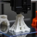
अन्य सभी 3 डी प्रिंटिंग प्रक्रियाओं (जैसे कि पॉलिमर 3 डी प्रिंटिंग) के समान, मेटल 3 डी प्रिंटर एक डिजिटल 3 डी डिज़ाइन के आधार पर एक समय में सामग्री को एक परत जोड़कर भागों का निर्माण करते हैं - इसलिए शब्द एडिटिव विनिर्माण शब्द। केवल इस बार, प्रक्रिया प्लास्टिक के बजाय धातु पाउडर, तार या बहुलक बाध्य फिलामेंट का उपयोग करती है।
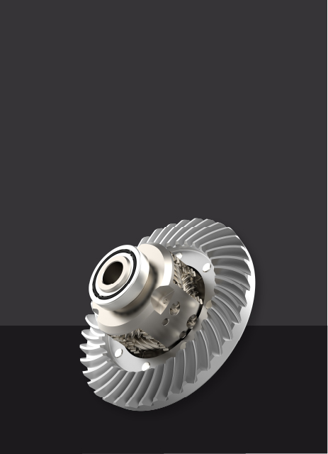
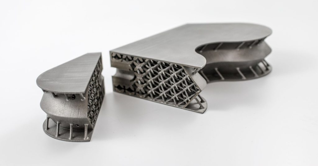
इस तरह, भागों को ज्यामिति के साथ बनाया जा सकता है जो पारंपरिक तरीकों के साथ निर्माण करना असंभव है और बिना मोल्ड या कटिंग टूल जैसे विशेष टूलिंग की आवश्यकता के बिना। बस के रूप में महत्वपूर्ण, बढ़ती ज्यामितीय जटिलता का निर्माण लागत पर बहुत कम प्रभाव पड़ता है, इसलिए कार्बनिक, टोपोलॉजी अनुकूलित संरचनाएं व्यावहारिक हैं। परिणामी भाग हल्के होते हैं (आमतौर पर 25% -50% वजन में कमी) और अक्सर स्टिफ़र, जो एयरोस्पेस और अन्य उच्च प्रदर्शन क्षेत्रों के लिए महत्वपूर्ण है।
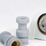
यह डिजाइन स्वतंत्रता भी विधानसभा समेकन को सक्षम करती है: कई घटक, और उनके सभी फास्टनरों, जोड़ों और रिसाव पथ, एक एकल मुद्रित हिस्सा बन सकते हैं जो एक बार में कई कार्य करता है। लेबर ड्रॉप्स, लीड टाइम्स सिकुड़ते हैं, और रखरखाव सरल है क्योंकि इकट्ठा करने, संरेखित करने या सेवा करने के लिए कम है। उस ने कहा, कई पारंपरिक तरीकों की तुलना में मेटल 3 डी प्रिंटिंग अभी भी महंगी है, और यह अभी तक उच्च मात्रा में इकाई लागत पर प्रतिस्पर्धा नहीं करता है।
धातु 3 डी प्रिंटिंग का एक संक्षिप्त इतिहास
1980 के दशक के उत्तरार्ध में, टेक्सास विश्वविद्यालय में डॉ। कार्ल डेकार्ड ने पहला लेजर सिन्टरिंग 3 डी प्रिंटर विकसित किया, जिसे शुरू में प्लास्टिक के लिए डिज़ाइन किया गया था। यह तकनीक चयनात्मक लेजर सिंटरिंग (एसएलएस) के लिए आधार बन गई, एक विधि जो बाद में धातु 3 डी प्रिंटिंग तक विस्तारित होगी।
1991 में, एमआईटी के डॉ। एली सैक्स ने एक 3 डी प्रिंटिंग प्रक्रिया शुरू की जिसे अब बाइंडर जेटिंग के रूप में जाना जाता है। मेटल बाइंडर जेटिंग की इस विधि को 1995 में एक्सोन करने के लिए लाइसेंस दिया गया था।
1995 में, जर्मनी में फ्राउनहोफर इंस्टीट्यूट ने धातुओं के लेजर पिघलने के लिए पहला पेटेंट दायर किया, जिसने आज मेटल 3 डी प्रिंटिंग के लिए सबसे व्यापक रूप से इस्तेमाल किए जाने वाले तरीकों में से एक चयनात्मक लेजर पिघलने (एसएलएम) के लिए नींव रखी। इस अवधि के दौरान, ईओएस और विभिन्न विश्वविद्यालयों जैसी कंपनियों ने प्रौद्योगिकी को और विकसित करने में महत्वपूर्ण भूमिका निभाई।
उपकरण और सामग्रियों की उच्च लागत के कारण 2000 के दशक की शुरुआत में धातु 3 डी प्रिंटिंग धीरे -धीरे बढ़ी। हालांकि, 2012 के आसपास, एसएलएम, डीएमएलएस, और ईबीएम जैसी प्रमुख प्रौद्योगिकियों के लिए पेटेंट के रूप में समाप्त होना शुरू हो गया, लाइसेंसिंग फीस गिरा, नए प्रतियोगियों के लिए दरवाजा खोलकर। इस बदलाव ने नवाचार को उकसाया और जीई, एचपी, और डीएमजी मोरी जैसी कंपनियों से प्रमुख निवेश को आकर्षित किया, लागत को कम किया और विभिन्न उद्योगों में गोद लेने में तेजी लाई।
आज,पूर्ववर्ती अनुसंधान रिपोर्ट के अनुसार, ग्लोबल मेटल 3 डी प्रिंटिंग मार्केट का मूल्य 2024 में USD 9.66 बिलियन है और 2025 में USD 12.04 बिलियन से बढ़कर 2034 तक USD 87.33 बिलियन से बढ़कर 24.63%का CAGR है। बाजार तेजी से प्रोटोटाइप, अनुकूलित और जटिल घटकों, और एयरोस्पेस और मोटर वाहन क्षेत्रों में बढ़ते उपयोग की मांग से प्रेरित है।
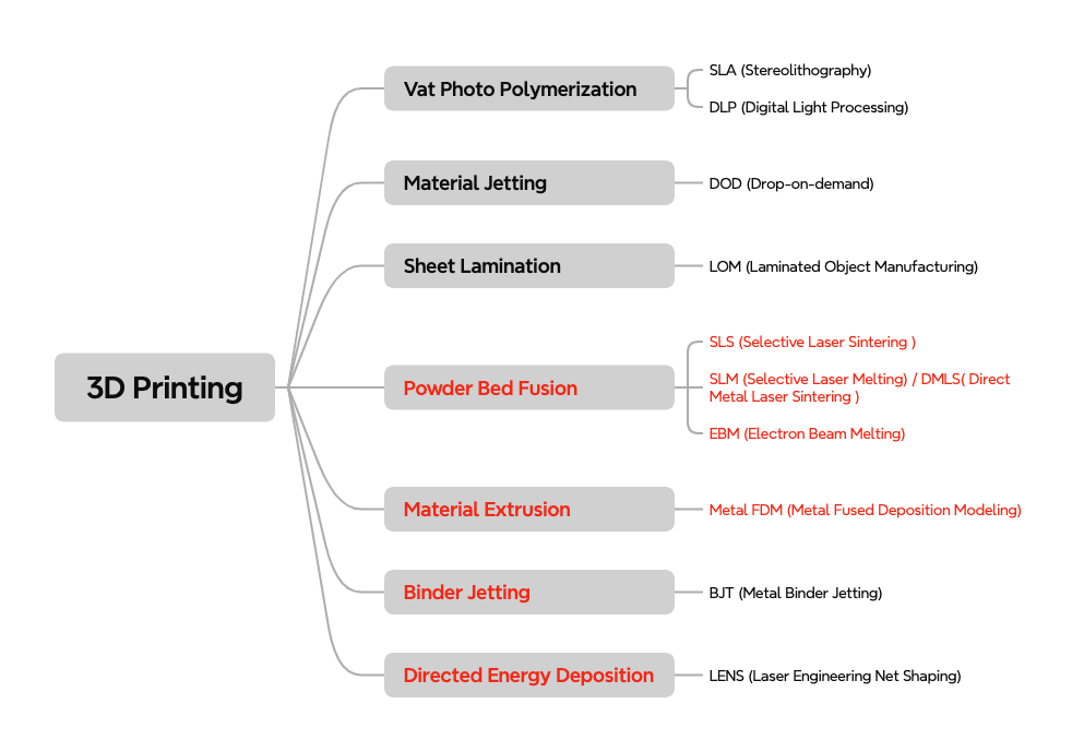
धातु 3 डी मुद्रण प्रौद्योगिकियों के प्रकार
बाजार पर कई धातु 3 डी प्रिंटिंग तकनीकें हैं, लेकिन सबसे व्यापक रूप से उपयोग किए जाने वाले चार पाउडर बेड फ्यूजन (पीबीएफ), बाइंडर जेटिंग, मेटल फ्यूज्ड डिपोजिशन मॉडलिंग (मेटल एफडीएम), और डायरेक्टेड एनर्जी डिपॉज़िट (डीईडी) हैं। मोटे तौर पर, वे दो तंत्रों में आते हैं: पिघलना और सिंटरिंग।
PBF और DED METAL METAL FEEDSTOCK (पाउडर या तार) उच्च ऊर्जा स्रोतों के साथ , जैसे लेज़रों, इलेक्ट्रॉन बीम, या ARCs, पूरी तरह से घने भागों के पास उत्पादन करने के लिए। इसके विपरीत, मेटल एफडीएम और बाइंडर जेटिंग पहले एक बहुलक बाइंडर के साथ एक "हरा" हिस्सा बनाएं, फिर डेबिंड और इसे पिघलने के बिंदु के नीचे सिन्टर करें। अंतिम घनत्व आमतौर पर पूरी तरह से पिघले हुए प्रक्रियाओं की तुलना में कम होता है, और अतिरिक्त पोस्ट प्रसंस्करण लगभग हमेशा आवश्यक होता है।
पाउडर बेड फ्यूजन (PBF)
पाउडर बेड फ्यूजन (पीबीएफ) को व्यापक रूप से सबसे अधिक इस्तेमाल किया जाने वाला धातु 3 डी प्रिंटिंग परिवार माना जाता है। इनमे से,चयनात्मक लेजर पिघलना (एसएलएम)औरप्रत्यक्ष धातु लेजर सिंटरिंग (डीएमएल), जो 20 से अधिक वर्षों से उपयोग में हैं, आज सबसे तकनीकी रूप से परिपक्व धातु 3 डी प्रिंटिंग प्रक्रियाएं हैं, इसके बाद, इसके बादइलेक्ट्रॉन बीम पिघलना (ईबीएम), एक अन्य प्रमुख विधि, विशेष रूप से एयरोस्पेस और मेडिकल अनुप्रयोगों में टाइटेनियम मिश्र धातुओं के लिए उपयोग की जाती है।
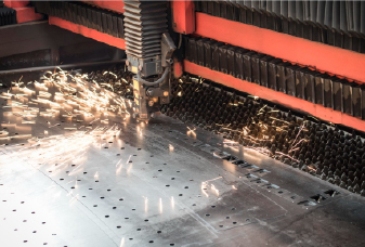
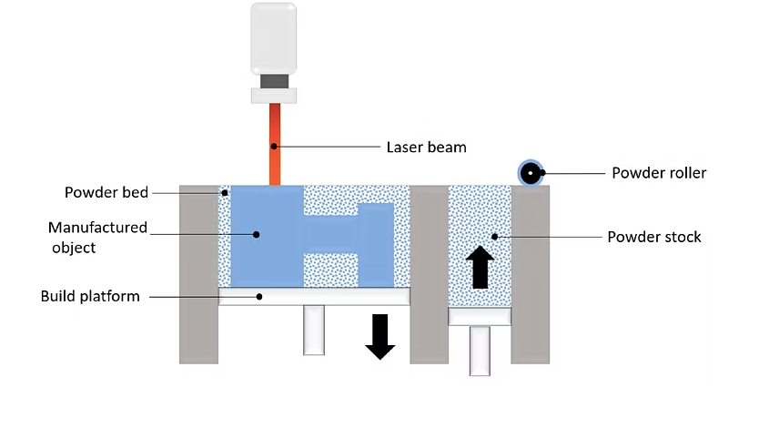
PBF प्रक्रिया बिल्ड चैंबर को प्रीहीट करके शुरू करती है, जो पहले एक अक्रिय गैस से भरी होती है, एक इष्टतम तापमान तक। धातु पाउडर की एक पतली परत तब बिल्ड प्लेटफॉर्म पर फैली हुई है। लेजर (एसएलएम और डीएमएलएस में) या इलेक्ट्रॉन बीम (ईबीएम में) को पाउडर बेड पर निर्देशित किया जाता है, जो कि भाग के डिजाइन के अनुसार पाउडर कणों को चुनिंदा या फ्यूजिंग करता है। कण पहली परत बनाने के लिए एक साथ फ्यूज करते हैं, और प्लेटफ़ॉर्म को फिर थोड़ा कम कर दिया जाता है। पाउडर की एक नई परत पिछले एक पर फैली हुई है, और प्रक्रिया को परत द्वारा दोहराया जाता है जब तक कि भाग पूरी तरह से निर्मित न हो जाए।
चूंकि निर्माण तापमान बहुत अधिक होता है (अक्सर कई मिश्र धातुओं के लिए 1000 ° C), समर्थन आमतौर पर भाग को रखने और थर्मल तनाव से युद्ध को रोकने के लिए आवश्यक होता है। ठंडा करने के बाद, अतिरिक्त अनमोल्ड पाउडर को हटा दिया जाता है (ब्रश किया जाता है, विस्फोट किया जाता है, या वैक्यूम किया जाता है), और समर्थन को काटकर या हटा दिया जाता हैवायर एडम।तब भाग को अवशिष्ट तनावों को दूर करने और भौतिक गुणों को बढ़ाने के लिए इलाज किया जाता है। अंत में, आवश्यकताओं के आधार पर, भाग को सीएनसी मशीनिंग जैसे अतिरिक्त परिष्करण की आवश्यकता हो सकती है,घर्षण, या अन्य सतह उपचार वांछित सतह की गुणवत्ता और आयामी सटीकता को प्राप्त करने के लिए।
आम पाउडर बिस्तर संलयन विधियों के लक्षण
यहाँ तीन मुख्य PBF धातु 3 डी प्रिंटिंग प्रौद्योगिकियों के लिए एक विस्तृत तुलना तालिका है:
संपत्ति
चयनात्मक लेजर पिघलना (एसएलएम)
प्रत्यक्ष धातु लेजर सिंटरिंग (डीएमएल)
इलेक्ट्रॉन बीम पिघलना (ईबीएम)
ऊर्जा स्रोत
लेज़र
लेज़र
इलेक्ट्रॉन किरण
उपयोग की गई सामग्री
एकल पिघलने वाले तापमान के साथ गोलाकार धातु पाउडर; एल्यूमीनियम मिश्र, टाइटेनियम, स्टेनलेस स्टील, टूल स्टील और कुछ मिश्र धातुओं को शामिल करें
चर पिघलने बिंदुओं के साथ गोलाकार धातु पाउडर; स्टेनलेस स्टील, टाइटेनियम मिश्र, निकेल मिश्र, कीमती धातुएं और टूल स्टील्स शामिल करें
गोलाकार धातु पाउडर जैसे कि टाइटेनियम मिश्र, कोबाल्ट-क्रोमियम मिश्र, निकेल सुपरलॉय और अन्य उच्च-प्रदर्शन सामग्री
प्रक्रिया
लेजर पूरी तरह से घने भागों को बनाने के लिए पाउडर को पिघला देता है
लेजर सिंटरिंग (पिघला हुआ पाउडर, लेकिन इसे पूरी तरह से तरलीकृत नहीं करता है)
इलेक्ट्रॉन बीम एक वैक्यूम वातावरण में पाउडर पिघला देता है
बिल्ड वॉल्यूम
आमतौर पर छोटे से मध्यम (मशीन द्वारा भिन्न होता है)
आमतौर पर छोटे से मध्यम (मशीन द्वारा भिन्न होता है)
आमतौर पर एसएलएम/डीएमएल की तुलना में बड़े बिल्ड वॉल्यूम उपलब्ध हैं
निर्माण गति
मध्यम (लेजर शक्ति और भाग जटिलता पर निर्भर करता है)
मध्यम (सामग्री और भाग के आकार के साथ भिन्न होता है)
धीमी (इलेक्ट्रॉन बीम और वैक्यूम वातावरण के उपयोग के कारण)
मुद्रित भाग गुण
आंतरिक छिद्र, 0.2 से कम - 0.5%; उच्च घनत्व और उत्कृष्ट यांत्रिक शक्ति
भाग गुण एसएलएम के समान हैं, लेकिन सिन्टरिंग प्रक्रिया के कारण मामूली पोरसिटी अधिक ध्यान देने योग्य हो सकती है
पोरसिटी आम तौर पर कम होती है, लेकिन यह धीमी गति से निर्माण गति और प्रक्रिया में बड़ी परत की मोटाई के कारण एसएलएम की तुलना में थोड़ा अधिक हो सकता है
आयामी सटीकता
± 0.1 मिमी
± 0.1 मिमी
± 0.1 मिमी
विशिष्ट निर्माण आकार
250 x 150 x 150 मिमी (500 x 280 x 360 मिमी तक)
250 x 150 x 150 मिमी (500 x 280 x 360 मिमी तक)
500 x 500 x 380 मिमी या बड़ा
सामान्य परत की मोटाई
20-50μM
20-50μM
50-150 माइक्रोन
सहायता
हमेशा आवश्यक
हमेशा आवश्यक
हमेशा आवश्यक
विशिष्ट सतह खुरदरापन
आरए 8 - 10μM
आरए 8 - 10μM
आरए 20-60 माइक्रोन
प्रति भाग लागत
$ $ $ $
$ $ $ $
$ $ $ $ $
प्रमुख अनुप्रयोग
उच्च ज्यामितीय जटिलता (कार्बनिक, टोपोलॉजी अनुकूलित संरचनाओं) वाले भागों में सबसे अधिक मांग वाले अनुप्रयोगों की दक्षता बढ़ाने के लिए उत्कृष्ट भौतिक गुणों की आवश्यकता होती है
एसएलएम के समान
उच्च-प्रदर्शन अनुप्रयोगों को मजबूत, लचीला भागों की आवश्यकता होती है, विशेष रूप से एयरोस्पेस और मेडिकल प्रत्यारोपण में, जहां टाइटेनियम मिश्र और अन्य उच्च शक्ति वाली सामग्रियों की आवश्यकता होती है
बाइंडर जेटिंग
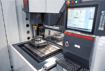
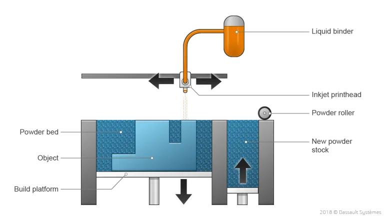
बाइंडर जेटिंग का उपयोग मूल रूप से सैंडस्टोन से पूर्ण-रंग प्रोटोटाइप और मॉडल बनाने के लिए किया गया था। समय के साथ, इसने धातु भागों के निर्माण के लिए लोकप्रियता हासिल की है, विशेष रूप से इसकी बैच उत्पादन क्षमताओं के कारण। मेटल बाइंडर जेटिंग प्रक्रिया के दौरान, मेटल पाउडर की एक पतली परत बिल्ड प्लेटफॉर्म पर फैली हुई है। इंकजेट नोजल से लैस एक गाड़ी फिर पाउडर बेड के ऊपर से गुजरती है, एक बाइंडिंग एजेंट की बूंदों को जमा करती है (आमतौर पर बहुलक और मोम का मिश्रण) धातु के कणों को एक साथ बांधने के लिए। एक बार एक परत पूरी हो जाने के बाद, बिल्ड प्लेटफ़ॉर्म नीचे चला जाता है, और पाउडर की एक नई परत लागू होती है। यह प्रक्रिया तब तक दोहराती है जब तक कि पूरा हिस्सा नहीं बन जाता।
मेटल बाइंडर जेटिंग में प्रिंटिंग स्टेप कमरे के तापमान पर होता है, थर्मल प्रभाव जैसे कि वारिंग और आंतरिक तनाव जैसे मुद्दों को समाप्त करता है जो डीएमएल और एसएलएम जैसी प्रक्रियाओं में हो सकता है। समर्थन संरचनाओं की आवश्यकता नहीं है। हालांकि, मुद्रित भाग "हरे" स्थिति में रहता है, जिसका अर्थ है कि यह अभी भी नाजुक है और आगे की प्रक्रिया की आवश्यकता है।
"हरे" भाग को पूरी तरह से ठोस धातु घटक में बदलने के लिए उपयोग किए जाने वाले दो सामान्य पोस्ट-प्रोसेसिंग चरण हैं:
घुसपैठ:बांधने की मशीन को हटाने के बाद, भाग को "भूरा" माना जाता है और इसमें महत्वपूर्ण आंतरिक पोरसिटी (लगभग 70%) है। "भूरा" भाग तब एक औद्योगिक ओवन में एक कम पिघलने बिंदु धातु (अक्सर कांस्य) के साथ गर्म किया जाता है, जो आंतरिक voids को भरता है, जिसके परिणामस्वरूप एक द्वि धातु का हिस्सा होता है। यद्यपि यह विधि ताकत में सुधार कर सकती है, यह आज आमतौर पर कम उपयोग किया जाता है क्योंकि इसके भौतिक गुण पूरी तरह से पापी भागों के लिए नीच हैं और इसके यांत्रिक और थर्मल प्रदर्शन के रूप में अच्छी तरह से प्रलेखित नहीं है।
Sintering:अब पसंदीदा पोस्ट-प्रोसेस, "हरे" भाग को एक भट्ठी में रखा जाता है जहां बाइंडर को जला दिया जाता है और धातु पाउडर कण एक साथ पूरी तरह से घने घटक में फ्यूज करते हैं। भाग आमतौर पर सिंटरिंग के दौरान लगभग 20% तक सिकुड़ता है, इसलिए भागों को क्षतिपूर्ति करने के लिए थोड़ा बड़ा मुद्रित किया जाता है।
धातु बाइंडर जेटिंग के लक्षण
संपत्ति
धातु बाइंडर जेटिंग
उपयोग की गई सामग्री
वर्तमान में स्टेनलेस स्टील्स (जैसे 316L, 17 4PH), टूल स्टील्स (जैसे H13), कांस्य/तांबे के मिश्र धातुओं और इनकम 625 तक सीमित
निर्माण गति
सभी धातु 3 डी प्रिंटिंग प्रौद्योगिकियों के बीच सबसे तेज़; बेड आमतौर पर घनी तरह से प्रति चक्र कई छोटे भागों के साथ पैक किए जाते हैं
मुद्रित भाग गुण
~ 1-2% अवशिष्ट पोरसिटी सिंटरिंग के बाद; कास्ट मेटल की तुलना में तन्य शक्ति, लेकिन आंतरिक voids के कारण थकान जीवन काफी कम है
आयामी सटीकता
± 0.2 मिमी (± 0.1 परीक्षण के बाद)
विशिष्ट निर्माण आकार
250 × 175 × 200 मिमी (400 × 300 × 200 मिमी तक)
सामान्य परत की मोटाई
शुरुआती सिस्टम 35-50 systemm, उच्च थ्रूपुट सिस्टम तक 100) m) चला
सहायता
आवश्यक नहीं
विशिष्ट सतह खुरदरापन
Ra10–15 onm पर पाप किए गए भागों के रूप में
प्रति भाग लागत
$ $ $ (तेजी से बिल्ड, और कोई समर्थन अपशिष्ट))
प्रमुख अनुप्रयोग
कार्यात्मक प्रोटोटाइप और जटिल घटकों के मध्यम रनों से कम जहां थ्रूपुट और यूनिट लागत अधिकतम यांत्रिक प्रदर्शन से अधिक है
धातु फ्यूज्ड डिपोजिशन मॉडलिंग (धातु एफडीएम)
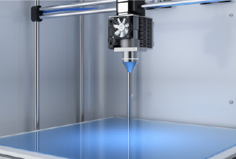
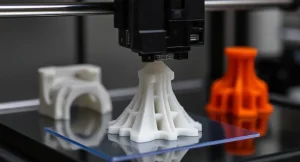
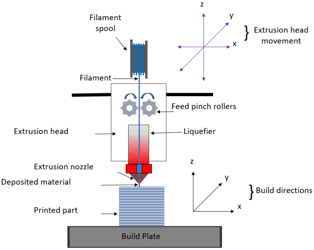
मेटल एक्सट्रूज़न प्लास्टिक के लिए क्लासिक एफडीएम प्रक्रिया की एक भिन्नता है, लेकिन थर्माप्लास्टिक के बजाय, यह धातु फिलामेंट्स या छड़ का उपयोग करता है जिसमें आमतौर पर बहुलक और/या मोम द्वारा एक साथ बंधे धातु के कण होते हैं, इसलिए इसे कभी -कभी फिलामेंट सामग्री एक्सट्रूज़न कहा जाता है।
इस रॉड या फिलामेंट को सीएडी मॉडल के आधार पर एक भाग बनाने के लिए एक गर्म नोजल और जमा परत-दर-परत के माध्यम से बाहर किया जाता है। उसी समय, यदि आवश्यक हो तो समर्थन संरचनाएं बनाई जाती हैं। समर्थन और भाग के बीच का इंटरफ़ेस एक सिरेमिक समर्थन सामग्री के साथ मुद्रित किया जाता है, जिसे बाद में मैन्युअल रूप से हटाना आसान है। परिणामी "हरे" भाग को बांधने के लिए स्टेप्स (लेकिन समान नहीं) का उपयोग करके धातु बनने के लिए पोस्ट-प्रोसेस किया जाना चाहिए। "हरे" भाग को पहले भिगोया जाता है या थर्मल रूप से अधिकांश बहुलक/मोम बाइंडर (डिबाइंडिंग) को हटाने के लिए इलाज किया जाता है, फिर एक भट्ठी में पाप किया जाता है ताकि धातु के कणों को एक घने, पूरी तरह से धातु के टुकड़े में फ्यूज कर दिया जाए। सिंटरिंग के दौरान भाग प्रत्येक दिशा में लगभग 15-20% सिकुड़ जाता है, इसलिए सीएडी मॉडल को पहले से बढ़ाया जाता है और कुछ ट्रायल ट्यूनिंग की आवश्यकता हो सकती है।
धातु फ्यूज्ड बयान मॉडलिंग के लक्षण
संपत्ति
धातु फ्यूज्ड डिपोजिशन मॉडलिंग
उपयोग की गई सामग्री
वर्तमान में 316L, 17 4PH, H13, कॉपर/कांस्य मिश्र धातुओं और इनकम 625 तक बहुत सीमित है
निर्माण गति
मध्यम; बाइंडर जेटिंग की तुलना में धीमा, लेकिन सेटअप/पुनरावृत्ति एसएलएम की तुलना में सस्ता और सरल है
मुद्रित भाग गुण
~ 90-97% घनत्व (कूल्हे के साथ ~ 98% तक); तन्यता ताकत मोटे तौर पर mim/कास्ट की तरह, आमतौर पर 20-40% कम से कम; अवशिष्ट छिद्र द्वारा थकान की ताकत कम
आयामी सटीकता
± 0.30 मिमी ठेठ; Tun 0.15–0.20 मिमी ट्यूनिंग और संकोचन मुआवजे के बाद प्राप्त करने योग्य है
विशिष्ट निर्माण आकार
250 × 220 × 200 मिमी
सामान्य परत की मोटाई
100-200 andm
सहायता
आवश्यक
विशिष्ट सतह खुरदरापन
Ra 10–20 on m पर sintered सतहों के रूप में
प्रति भाग लागत
$ $ (कम मशीन/सामग्री लागत)
प्रमुख अनुप्रयोग
कार्यात्मक धातु प्रोटोटाइप, कस्टम टूलींग, और एक बंद/कम मात्रा वाले भागों जहां लागत और सादगी चरम प्रदर्शन से अधिक मायने रखते हैं
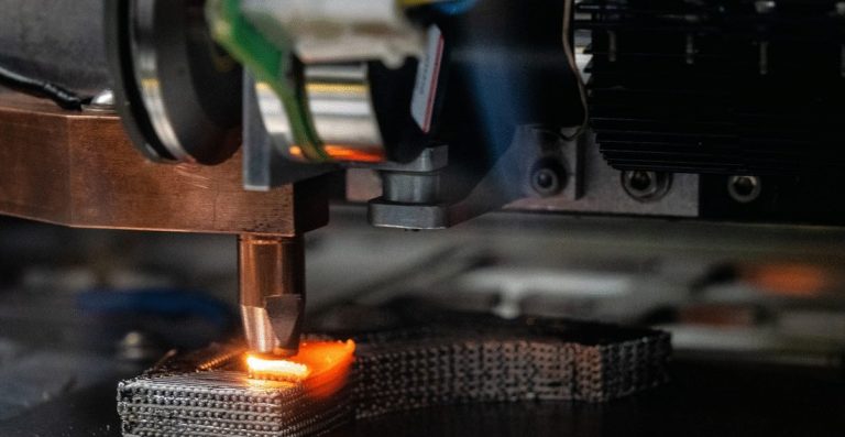
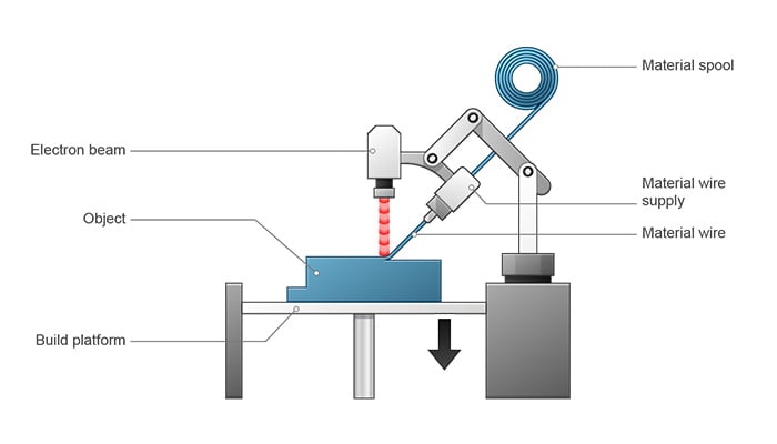
निर्देशित ऊर्जा जमाव (डीईडी)
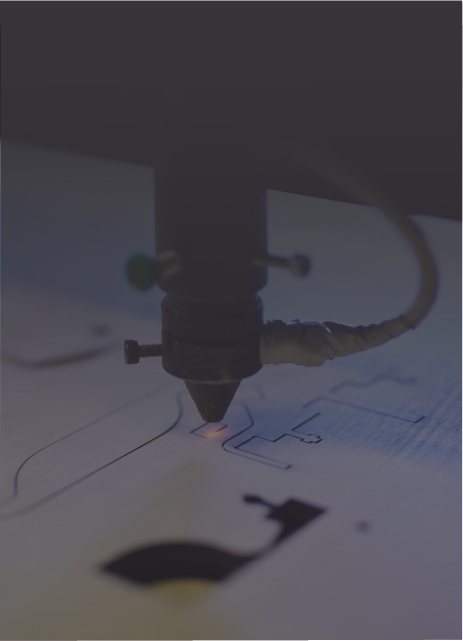
निर्देशित ऊर्जा जमाव (डीईडी) एक केंद्रित गर्मी स्रोत का उपयोग करता है, आमतौर पर एक लेजर, इलेक्ट्रॉन बीम, या इलेक्ट्रिक/प्लाज्मा आर्क, वर्कपीस पर एक पिघल पूल बनाने के लिए, जबकि धातु पाउडर या तार को इसमें खिलाया जाता है, बीड द्वारा निर्माण सामग्री मनका। क्योंकि प्रिंट हेड स्वतंत्र रूप से स्थानांतरित कर सकता है (अक्सर मल्टी एक्सिस गंट्रीज़ या रोबोट पर) और एक पाउडर बेड द्वारा सीमित नहीं होता है, डीडेड्स मौजूदा भागों में सुविधाओं की मरम्मत या जोड़ने के लिए अच्छी तरह से अनुकूल है और बड़े उत्पादन के लिए, शुद्ध आकार के घटकों के पास, व्यापार ऑफ्स मोटे मनके ज्यामिति, खुरदरी सतहों, और महत्वपूर्ण थर्मल इनपुट को पूरा करने के लिए हैं, जो आमतौर पर गर्म करने के लिए आवश्यक हैं।
निर्देशित ऊर्जा जमाव के लक्षण
संपत्ति
निर्देशित ऊर्जा बयान
ऊर्जा स्रोत
केंद्रित लेजर, इलेक्ट्रॉन बीम, या इलेक्ट्रिक/प्लाज्मा आर्क
उपयोग की गई सामग्री
SLM के लिए समान मिश्र धातु रेंज; मानक वेल्डिंग तारों और कई वेल्डेबल पाउडर प्रयोग करने योग्य हैं
निर्माण गति
(या नीचे) बाइंडर जेटिंग के लिए तुलनीय
मुद्रित भाग गुण
~ 95-99% घनत्व (वायर फीड अक्सर पाउडर से अधिक होता है); दिशात्मक गुणों के साथ माइक्रोस्ट्रक्चर की तरह वेल्ड; तन्यता ताकत उचित गर्मी उपचार के बाद गढ़ा जा सकती है
आयामी सटीकता
± 0.5–1.0 मिमी विशिष्ट
विशिष्ट निर्माण आकार
आम तौर पर चार में से सबसे बड़ा
सामान्य परत की मोटाई
0.3-1.5 मिमी (तार) या 0.2–0.8 मिमी (पाउडर), नोजल और पावर के आधार पर
सहायता
आम तौर पर आवश्यक नहीं; पाथ प्लानिंग या अस्थायी फिक्स्चर के माध्यम से ओवरहैंग्स को संभाला
विशिष्ट सतह खुरदरापन
आरए> 20-40µm
प्रति भाग लागत
$ $ - $ $ $ (उपकरण महंगा है, लेकिन उच्च बयान दर बड़े भागों/मरम्मत के लिए लागत कम है)
प्रमुख अनुप्रयोग
मरम्मत/नवीनीकरण, सुविधा जोड़, बड़े संरचनात्मक घटक, बाद की मशीनिंग के लिए शुद्ध आकार के रिक्त स्थान के पास
धातु 3 डी मुद्रण के लिए सामग्री
जबकि व्यापक रूप से उपयोग किए जाने वाले इंजीनियरिंग धातुओं जैसे कि स्टेनलेस स्टील्स, टाइटेनियम, और एल्यूमीनियम मिश्र धातुएं धातु 3 डी प्रिंटिंग के लिए उपलब्ध हैं, पारंपरिक विनिर्माण में उपयोग किए जाने वाले कई अन्य उच्च प्रदर्शन या कस्टम मिश्र अभी भी स्रोत के लिए कठिन हैं या एएम के लिए अर्हता प्राप्त करते हैं। क्योंकि प्रिंट करने योग्य पाउडर आमतौर पर गैस को गोलाकार, संकीर्ण आकार और ऑक्सीजन में कम करने के लिए परमाणु होते हैं, वे कम मिश्र धातुओं में उपलब्ध, और अभी भी अपेक्षाकृत कम उपज पर उत्पादित करने के लिए महंगा है। उस ने कहा, धातु 3 डी प्रिंटिंग के लिए उपलब्ध धातुओं की संख्या तेजी से बढ़ रही है। इंजीनियर आज निकेल आधारित और कोबाल्ट क्रोमियम सिस्टम सहित मिश्र धातुओं से चयन कर सकते हैं - पारंपरिक रूप से मशीन के लिए कुख्यात हैं।
नीचे आम एएम धातुओं के कुछ उदाहरण दिए गए हैं, स्टेनलेस स्टील्स, टाइटेनियम, और एल्यूमीनियम के साथ अभी भी सबसे व्यापक रूप से उपयोग किए जाने वाले हैं:
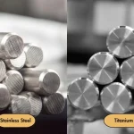
स्टेनलेस स्टील्स
टूल स्टील्स
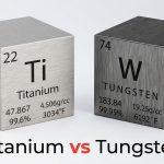
टाइटेनियम मिश्र धातु
एल्यूमीनियम मिश्र धातु
निकेल आधारित सुपरलॉय
कोबाल्ट क्रोमियम मिश्र धातु
तांबा आधारित मिश्र धातु
कीमती धातुएं (सोना, चांदी, प्लैटिनम, आदि)
विदेशी धातु (पैलेडियम, टैंटलम, आदि)
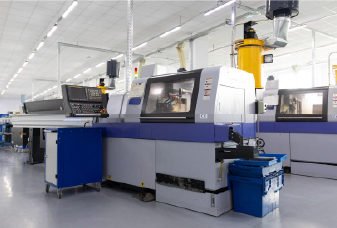
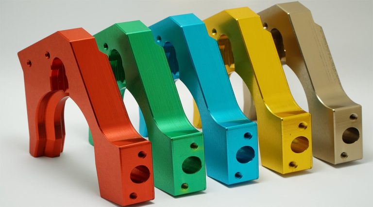
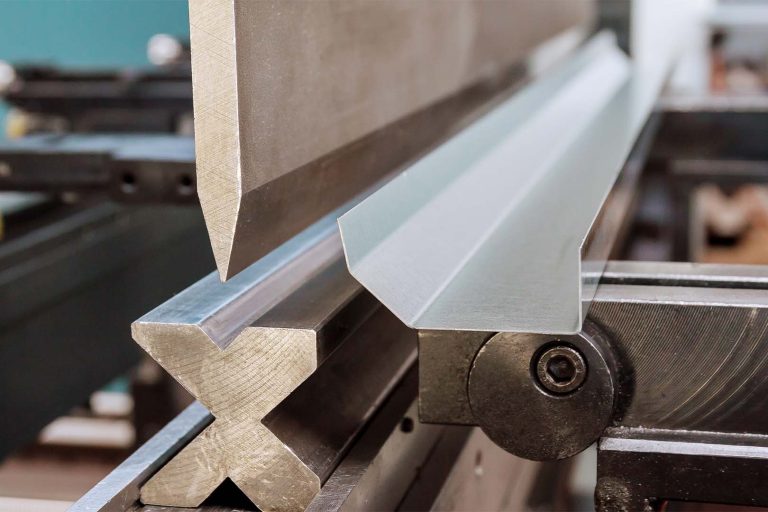
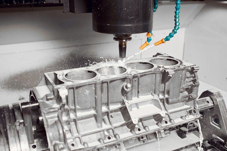
धातु 3 डी प्रिंटिंग बनाम पारंपरिक विनिर्माण
जब आपको केवल कुछ जटिल, उच्च प्रदर्शन धातु भागों की आवश्यकता होती है, तो टूलींग आधारित विधियां धीमी और महंगी होती हैं। मेटल 3 डी प्रिंटिंग टूलिंग से बचती है और जटिल ज्यामिति को सीधा बनाती है। सरल डिजाइनों या बड़ी मात्रा में, सीएनसी मशीनिंग या कास्टिंग आमतौर पर सस्ता और तेज होता है। नीचे इस बात का अवलोकन किया गया है कि मेटल 3 डी प्रिंटिंग की तुलना घटाव (सीएनसी मशीनिंग) और प्रमुख पहलुओं में औपचारिक (कास्टिंग) प्रक्रियाओं के साथ की जाती है।
पहलू
धातु 3 डी मुद्रण
सीएनसी मशीनिंग
धातु कास्टिंग
डिजाइन स्वतंत्रता
जटिल/आंतरिक चैनलों, जाली, भाग समेकन के लिए उत्कृष्ट
टूल एक्सेस और कटर ज्यामिति द्वारा सीमित
कार्बनिक बाहरी आकृतियों के लिए अच्छा है, लेकिन पूरी तरह से संलग्न चैनलों के साथ ड्राफ्ट/कोर और संघर्ष की आवश्यकता है
टूलींग / सेटअप
कोई मोल्ड या कटिंग टूल नहीं; केवल स्लाइसिंग/सपोर्ट सेटअप
कोई मोल्ड नहीं, लेकिन फिक्सिंग और कैम प्रोग्रामिंग की जरूरत है
मोल्ड्स/डाइस/कोर की आवश्यकता होती है; उच्च अग्रिम समय और लागत
लेड टाइम (प्रोटोटाइप)
घंटों की दिनांक
दिन (प्रोग्रामिंग + मशीनिंग)
सप्ताह -महीने (टूलींग का निर्माण)
यूनिट लागत बनाम
फ्लैट/उच्च प्रति भाग; उच्च मात्रा में खराब तरीके से
वॉल्यूम के साथ घटता है, लेकिन प्रत्येक भाग को अभी भी मशीन समय की आवश्यकता होती है।
उच्च मात्रा में बहुत कम; टूलींग के बाद पैमाने की उत्कृष्ट अर्थव्यवस्थाएं
आयामी सटीकता
मध्यम; संकोचन/थर्मल प्रभाव, प्रक्रिया पर निर्भर (Pb 0.1–0.3 मिमी पीबीएफ के लिए ठेठ)।
उच्च; सटीक सुविधाओं पर ± 0.01–0.05 मिमी आम
मध्यम; ± 0.1–0.5 मिमी विशिष्ट (निवेश <रेत)
सतह खत्म (जैसा कि बनाया हुआ)
किसी न किसी (ra ~ 5–20+µm); खत्म होने की आवश्यकता होती है
अच्छी तरह से उत्कृष्ट
निष्पक्ष -रस; आमतौर पर मशीनिंग/पॉलिशिंग की आवश्यकता होती है
यांत्रिक विशेषताएं
उचित एचटी/कूल्हे के बाद ताकत की ताकत कर सकते हैं, लेकिन पोरसिटी और सतह के कारण अक्सर थकान कम होती है; तनाव से राहत/हिप की सिफारिश की गई
गढ़ा स्टॉक → अनुमानित, उच्च यांत्रिक प्रदर्शन का उपयोग करता है
कास्ट माइक्रोस्ट्रक्चर; तन्यता और थकान गुण आम तौर पर नीचे गढ़े हुए हैं, लेकिन गर्मी उपचार (और कभी -कभी कूल्हे) के साथ सुधार किया जा सकता है
भाग का आकार
बिल्ड चैंबर द्वारा सीमित (डीईडी को छोड़कर)
मशीन लिफाफे द्वारा सीमित; बड़ी मिलें मौजूद हैं
बहुत बड़े हिस्से संभव (रेत कास्टिंग, निवेश कास्टिंग)
सामग्री सीमा
बढ़ते हुए लेकिन अभी भी कम योग्य मिश्र धातु
लगभग किसी भी मशीन योग्य धातु
बहुत व्यापक; अधिकांश मिश्र धातु, हालांकि कुछ मुश्किल हैं
अपशिष्ट / सामग्री दक्षता
कम; अप्रयुक्त पाउडर अक्सर पुनर्नवीनीकरण किया जाता है
उच्च चिप अपशिष्ट (जब तक अलग से पुनर्नवीनीकरण नहीं किया जाता है)
मध्यम अपशिष्ट (गेटिंग/रिसर स्क्रैप)
प्रोसेसिंग के बाद
सहिष्णुता के लिए समर्थन हटाने, गर्मी उपचार, हिप, मशीनिंग
बहस, संभव गर्मी उपचार, परिष्करण
फेटलिंग, हीट ट्रीटमेंट, मशीनिंग टू फाइनल टॉलरेंस
सबसे अच्छा उपयोग मामले
जटिल, कम मात्रा, उच्च मूल्य भागों; तेजी से पुनरावृत्ति; आंतरिक चैनल/जाली
तंग सहिष्णुता, मध्यम संस्करणों के साथ सटीक भाग
उच्च मात्रा या बहुत बड़े हिस्से जहां टूलींग लागत को परिशोधन किया जा सकता है
पारंपरिक विनिर्माण पर धातु मुद्रण चुनें
1।ज्यामिति ड्राइव प्रदर्शन
आंतरिक चैनल, जाली infill, अनुरूप शीतलन पथ, और समेकित, एक टुकड़ा असेंबली मशीन या कास्ट के लिए कठिन या असंभव है।
2। कम मात्रा
यदि आपको केवल 1-50 भागों जैसे कि प्रोटोटाइप, पायलट रन, या पुर्जों की आवश्यकता होती है, तो टूलींग आधारित तरीके शायद ही कभी भुगतान करते हैं। एडिटिव मैन्युफैक्चरिंग मोल्ड्स और डाइस से बचता है, यूनिट की लागत को अपेक्षाकृत कम मात्रा में और उचित रूप से कम मात्रा में रखता है।
3। फास्ट डिज़ाइन पुनरावृत्ति
बस सीएडी फ़ाइल को अपडेट करें, फिर से स्लाइस करें, और प्रिंट करें - कोई नया जुड़नार या मोल्ड नहीं। सीएनसी को फिर से तैयार किया जा सकता है, लेकिन अक्सर अभी भी स्थिरता/उपकरण परिवर्तन की आवश्यकता होती है, जबकि कास्टिंग लगभग हमेशा नए या संशोधित टूलिंग की मांग करता है।
4।लीड समय इकाई लागत से अधिक मायने रखता है
एक जटिल धातु भाग को अक्सर कुछ दिनों में मुद्रित किया जा सकता है - कास्टिंग टूल बनाने और साबित करने के लिए आवश्यक 6-8 सप्ताह से अधिक तेज। एओजी (जमीन पर विमान) स्थितियों या तत्काल टूलींग के लिए, प्रति टुकड़ा मूल्य गति ट्रम्प।
5। मशीन मिश्र धातुओं के लिए कठिन
Inconel, Co Cr और अन्य सुपरलॉय को काटने के लिए महंगा है: वे कड़ी मेहनत कर रहे हैं, जल्दी से कठोर काम करते हैं, और उपकरणों को नष्ट कर देते हैं। मेटल 3 डी प्रिंटिंग स्किप्स सबसे कटिंग, टूल वियर और हीट के मुद्दों से परहेज। एसएलएम या ईबीएम जैसी उच्च ऊर्जा प्रक्रियाएं टंगस्टन (3422 डिग्री सेल्सियस) जैसे अल्ट्रा उच्च पिघलने बिंदु धातुओं से घटकों का निर्माण कर सकती हैं जो कुशलता से मशीन के लिए लगभग असंभव हैं।
6। भौतिक अपशिष्ट को कम करें (मक्खी के अनुपात में खरीदें)
पारंपरिक मशीनिंग एक एयरोस्पेस बिललेट के 80-90% को स्क्रैप कर सकता है। पाउडर बेड एएम के साथ, अधिकांश अप्रयुक्त पाउडर को छलनी और पुन: उपयोग किया जा सकता है, इसलिए आप शुद्ध आकार के पास बहुत करीब हैं; उदाहरण के लिए, एक टाइटेनियम ब्रैकेट को ~ 6 × के बजाय केवल ~ 1.2 × इसके अंतिम द्रव्यमान की आवश्यकता हो सकती है।
7। मांग पर या साइट उत्पादन पर
प्रिंटिंग स्पार्स जहां आप उन्हें स्लैश इन्वेंट्री और लॉजिस्टिक्स का उपयोग करते हैं। एक अपतटीय रिग एक मशीनी प्रतिस्थापन के लिए हफ्तों की प्रतीक्षा के बजाय साइट पर एक कस्टम स्टेनलेस वाल्व हैंडल प्रिंट कर सकता है।
8। मौजूदा भागों में सुविधाएँ या जोड़ें
निर्देशित ऊर्जा जमाव टरबाइन ब्लेड युक्तियों को पहना जाता है या एक महंगे आवास में मालिकों को जोड़ता है। बयान के बाद, सीएनसी फिनिशिंग सटीक प्रोफाइल को पुनर्स्थापित करता है, अक्सर पूरे हिस्से को फिर से तैयार करने की तुलना में सस्ता होता है।
9। टोपोलॉजी अनुकूलन और लाइटवेटिंग
AM आपको कार्बनिक, अनुकूलित ज्यामितीयों का एहसास करने देता है जो गैर -लोड असर द्रव्यमान को हटाते हैं। जाली इन्फिल के साथ पुन: डिज़ाइन किया गया एक एयरोस्पेस काज ताकत बनाए रखते हुए लगभग 40% तक वजन कम कर सकता है, जिसके परिणामस्वरूप मिल या कास्ट के लिए अव्यवहारिक होता है।
10। विधानसभा समेकन
मशीनिंग के बजाय एक एकीकृत भाग प्रिंट करें और कई टुकड़ों को एक साथ जोड़ें। उदाहरण के लिए, कई रिसाव पथों के साथ एक 12 पीस हाइड्रोलिक कई गुना आंतरिक चैनलों के साथ एक एकल मुद्रित ब्लॉक बन सकता है। इसका मतलब है कम फास्टनर, कम जोड़ों, कम विधानसभा समय और उच्च विश्वसनीयता।
11। कस्टम या ग्रेडेड सामग्री
विभिन्न क्षेत्रों में एक आला मिश्र धातु या विभिन्न गुणों की आवश्यकता है? कुछ एएम सिस्टम (विशेष रूप से डीईडी) रचना ग्रेडिएंट बनाने के लिए निर्माण के दौरान पाउडर या तारों को स्विच कर सकते हैं। अनुसंधान दल हड्डी एकीकरण के लिए नरम क्षेत्रों के साथ टीआई -एनबी प्रत्यारोपण प्रिंट करते हैं और लोड असर के लिए स्टिफ़र वर्गों, सभी एक बिल्ड में।
धातु 3 डी मुद्रण की लागत
मेटल 3 डी प्रिंटिंग आमतौर पर प्लास्टिक की तुलना में अधिक महंगी होती है क्योंकि लागत तीन क्षेत्रों में अधिक होती है: उपकरण, सामग्री और पोस्ट प्रोसेसिंग ऑपरेशंस। नीचे दिए गए खंड प्रत्येक पर विस्तार से चर्चा करते हैं।
उपकरण लागत
धातु प्रिंटर कहीं अधिक जटिल हैं: उच्च शक्ति लेजर या इलेक्ट्रॉन बीम, अक्रिय गैस या वैक्यूम कक्ष, मल्टी लेजर स्कैन सिस्टम, सटीक प्रकाशिकी, और नियंत्रित पाउडर डिलीवरी - एफडीएम या फोटोपॉलीमर मशीनों की तुलना में सभी बहुत दूर। प्रौद्योगिकी द्वारा विशिष्ट मूल्य सीमाएँ:
धातु 3 डी प्रिंटिंग सामग्री भी ठेठ प्लास्टिक से अधिक खर्च होती है। धातु फीडस्टॉक्स के बीच, परमाणु पाउडर सबसे महंगा है क्योंकि इसे उच्च गोलाकारता, एक संकीर्ण कण-आकार की सीमा और बहुत कम ऑक्सीजन सामग्री के साथ उत्पादित किया जाना चाहिए। डीएडी के लिए तार आमतौर पर पाउडर की तुलना में सस्ता होता है, जबकि बहुलक बाध्य धातु फिलामेंट (धातु एफडीएम में उपयोग किया जाता है) अभी भी सस्ता है।
परमाणु पाउडर (एसएलएम, बाइंडर जेटिंग): लगभग $ 100- $ 600 प्रति किलोग्राम, मिश्र धातु पर निर्भर करता है (कम अंत में स्टेनलेस, उच्च अंत में टीआई/एनआई)
तार (DED): लगभग $ 20- $ 80 प्रति किलोग्राम; पाउडर-खिलाया गया डीड पाउडर-बेड की कीमतों के करीब है
पॉलिमर-बाउंड मेटल फिलामेंट (मेटल एफडीएम): लगभग $ 50- $ 150 प्रति किलोग्राम
प्रोसेसिंग के बाद
समर्थन हटाने, तनाव राहत चक्र, हिप, सीएनसी परिष्करण, और सतह उपचार सैकड़ों या यहां तक कि हजारों डॉलर प्रति बिल्ड या प्रति भाग जोड़ सकते हैं। बाइंडर जेटिंग और मेटल एफडीएम को भी डिबाइंडिंग और सिंटरिंग की आवश्यकता होती है, जो भट्ठी समय और लागत को जोड़ते हैं।
नीचे दी गई तालिका विशिष्ट DMLS/SLM लागत योगदानकर्ताओं का टूटना है। ध्यान दें कि पोस्ट प्रोसेसिंग कुल का एक महत्वपूर्ण हिस्सा कैसे बनाती है।
उत्पादन चरण
संचालन
विशिष्ट लागत*
उत्पादन
धातु पाउडर
$ 200- $ 500 प्रति किलोग्राम (सामग्री पर निर्भर)
मशीन का समय (एक बिल्ड प्लेट)
$ 2,000- $ 4,000
प्रोसेसिंग के बाद
तनाव राहत चक्र
$ 500- $ 600 प्रति बिल्ड
भाग/समर्थन हटाने
$ 100- $ 200 प्रति भाग
गर्मी उपचार / कूल्हे
$ 500- $ 2,500 प्रति बिल्ड
सीएनसी मशीनिंग
$ 500- $ 2,000 प्रति भाग
सतह परिष्करण / कोटिंग
$ 200- $ 500 प्रति भाग
* वास्तविक संख्या ज्यामिति, बैच आकार, सामग्री, क्षेत्र के साथ भिन्न होती है, और दुकान ओवरहेड कैसे आवंटित होती है। एक एकल बिल्ड प्लेट भाग के आकार के आधार पर 1-12 भागों (या अधिक) को पकड़ सकती है।
इसके अलावा, उपभोज्य अक्रिय गैस, भट्ठी और लेजर पावर, पाउडर सिविंग और परीक्षण, धूल विस्फोट/ऑक्सीकरण सुरक्षा उपाय, और चल रहे रखरखाव और अंशांकन सभी धातु 3 डी प्रिंटिंग की परिचालन लागत को प्लास्टिक प्रिंटिंग की तुलना में काफी अधिक बनाते हैं।
निष्कर्ष
धातु 3 डी प्रिंटिंग की क्षमता आज के एयरोस्पेस और मेडिकल उपयोग से परे है। अधिक मिश्र, होशियार मशीनों, और आसान पोस्ट प्रसंस्करण के रूप में ऑनलाइन आते हैं, कई क्षेत्रों में कंपनियां इसका उपयोग वास्तविक दुनिया के प्रदर्शन को मान्य करने और अनुकूलित, जटिल धातु भागों पर लागत में कटौती करने के लिए करेंगी। यदि आप धातु एएम के साथ अपनी क्षमताओं का विस्तार करने के बारे में सोच रहे हैं,संपर्क में रहो। हमारी टीम आपको यह तय करने में मदद कर सकती है कि यह कब और कैसे समझ में आता है।